00198829-01_SM_X-Series-S_Hxxxx_EN.pdf - 第86页
5 Pneumatic System 5.2 Disabling the compressed air supply 86 Service Manual SIPLACE X-Series S (from Hxxxx) 01/2021 5.2 Disabling the compressed air supply CAUTION Switch off the compressed air supply Th e co m pr es s …
5 Pneumatic System
5.1 Pneumatic System - Overview
Service Manual SIPLACE X-Series S (from Hxxxx) 01/2021 85
5 Pneumatic System
DANGER
Observe User Manual
► Please observe the safety instructions in the user manual for all work!
CAUTION
Switch off the compressed air supply
When working on the pneumatic system, always disconnect the machine from the com-
pressed air supply.
CAUTION
Use the correct blanking plugs
► Only use blanking plugs in the machine which match the manufacturer's compressed
air connection. A tight fit cannot be guaranteed for other blanking plugs.
► We recommend the use of blanking plugs made by Festo.
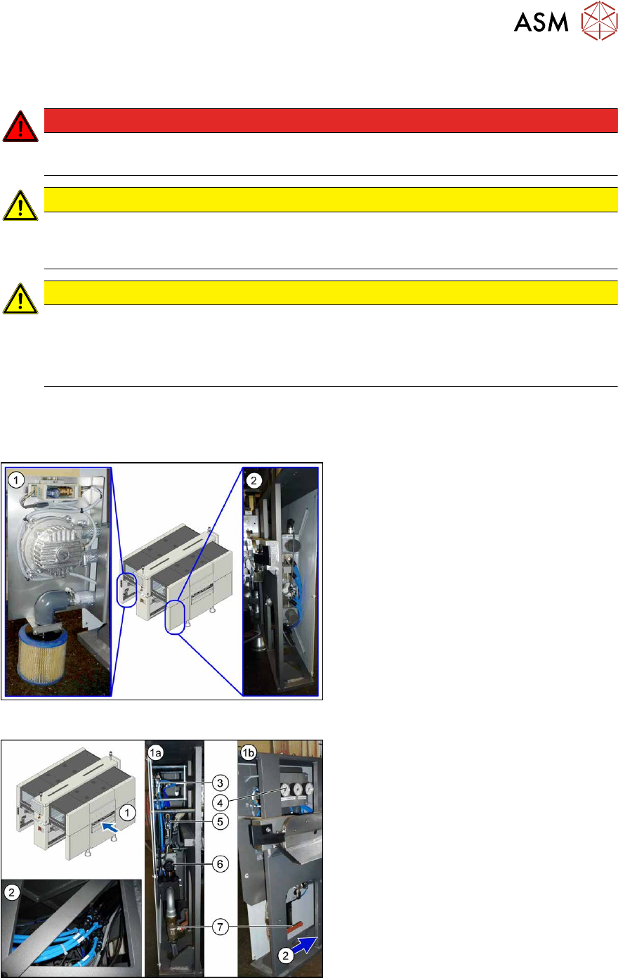
5.1 Pneumatic System - Overview
The pneumatic system is located at locations 1, 3 and 4, behind the side covers.
Fig.97: Pneumatics (location 3 and 4)
1. Location 3, behind the side cover:
Elmo blower with electrics, cooling air
filter
2. Location 4, behind the side cover:
Proportional controller for gantry group
placement heads PA1/PA2
Fig.98: Pneumatics (location 1)
1. Location 1, behind the side cover:
1a) View from front
1b) View from side
Connection coupling, main valve with
compressed air filter, compressed air
displays
2. Location 1, at the bottom, in the
machine base: compressed air connec-
tion for gantry trailing cable and
vacuum pump
3. 5/2 way valve [03062277-xx]
Main valve (X59) for NC, insert, conveyor
4. Manometer
5. 5/2 solenoid valve [00344974-xx]
Safety valve (X60) for tape cutter
6. Pressure regulator [03062103-xx]
7. Main valve
5 Pneumatic System
5.2 Disabling the compressed air supply
86 Service Manual SIPLACE X-Series S (from Hxxxx) 01/2021
5.2 Disabling the compressed air supply
CAUTION
Switch off the compressed air supply
The compressed air supply must always be switched off for all work on the pneumatic system.
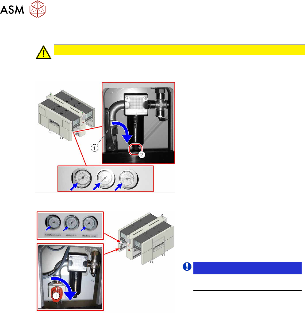
Fig.99: Disabling the compressed air supply (version 1)
Version 1:
► Push the lever (1) for the compressed
air supply down until it is positioned ho-
rizontally.
► Open the screw (2) on the inlet filter to
vent the system. Hold a cloth under-
neath to capture any escaping liquid.
Fig.100: Shutting off the compressed air supply (version 2)
Version 2:
► Push the switch (1) for the compressed
air supply by 90 degrees, until it is posi-
tioned horizontally.
► All pressure gauges must be set to
zero.
NOTICE!
Venting is performed automatically
in this version.
.
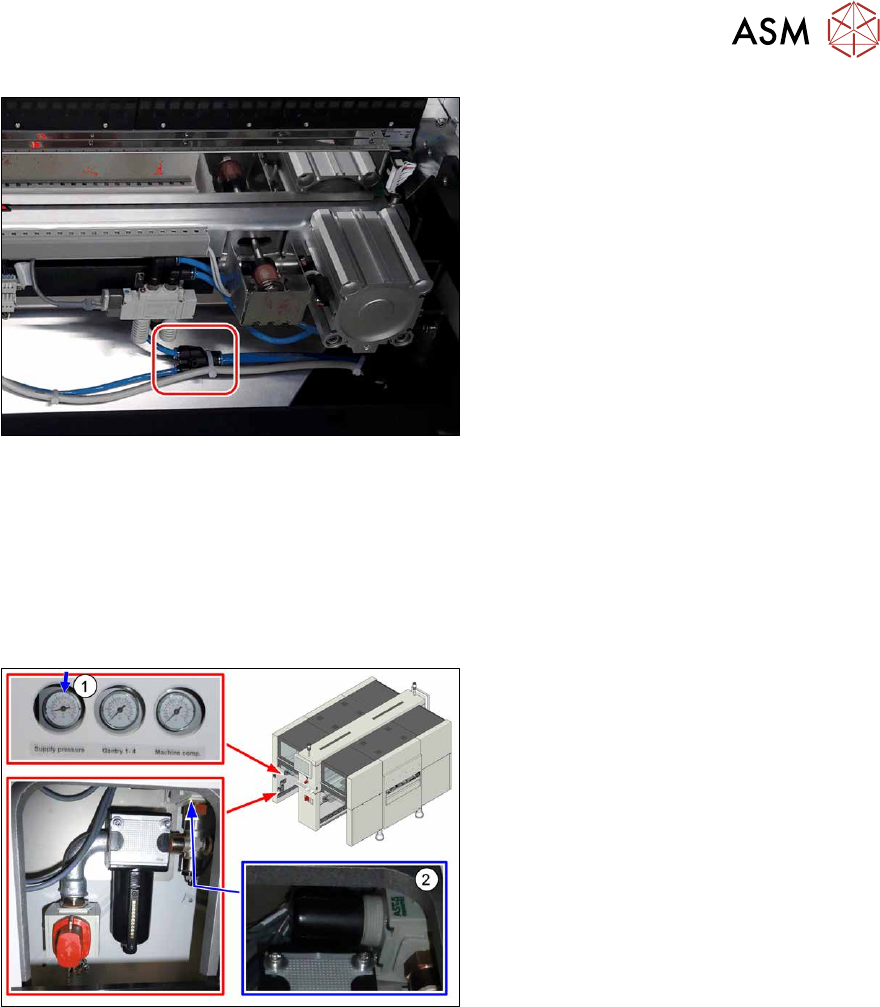
If you are working on cutters, you will need to vent these as follows:
5 Pneumatic System
5.3 Setting the pressure for the machine components
Service Manual SIPLACE X-Series S (from Hxxxx) 01/2021 87
Fig.101: Venting the cutter (example of SIPLACE SX1V2 shown)
► Pull one of the thinner pneumatic hoses
of the T-section on the cutter.
See also
2 1.1.5 "Safety instructions for work on the cutting device" [}15]
2 1.1.4 "Safety instructions for the compressed air supply" [}15]
5.3 Setting the pressure for the machine components
Fig.102: Pressure for machine components
► Make sure that the pressure for
machine components is set to
5.1bar(1)
.
► Correct the pressure where necessary,
with the pressure control valve(2)
.