00198829-01_SM_X-Series-S_Hxxxx_EN.pdf - 第91页
5 Pneumatic System 5.7 Replacing the safety valve for the cutters (location 1) Service Manual SIPLACE X-Series S (from Hxxxx) 01/2021 91 5.7 Replacing the safety valve for the cutters (location 1) Parts Fig.107: Safety …
5 Pneumatic System
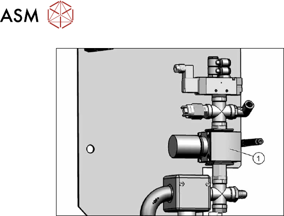
5.6 Replacing the pressure regulator (location 1)
90 Service Manual SIPLACE X-Series S (from Hxxxx) 01/2021
Fig.106: Pressure control valve
► Loosen the screwed clamps at the top
and bottom of the pressure control
valve.(1)
.
► Carefully remove the pressure control
valve.
Installation
Follow the removal instructions in reverse order for installation. Also observe the following instruc-
tions:
► Seal the compressed air system with sealant. Observe the instructions in section 5.4 "Sealing
the Pneumatic Screwed Connections" [}88] in connection with this.
5 Pneumatic System
5.7 Replacing the safety valve for the cutters (location 1)
Service Manual SIPLACE X-Series S (from Hxxxx) 01/2021 91
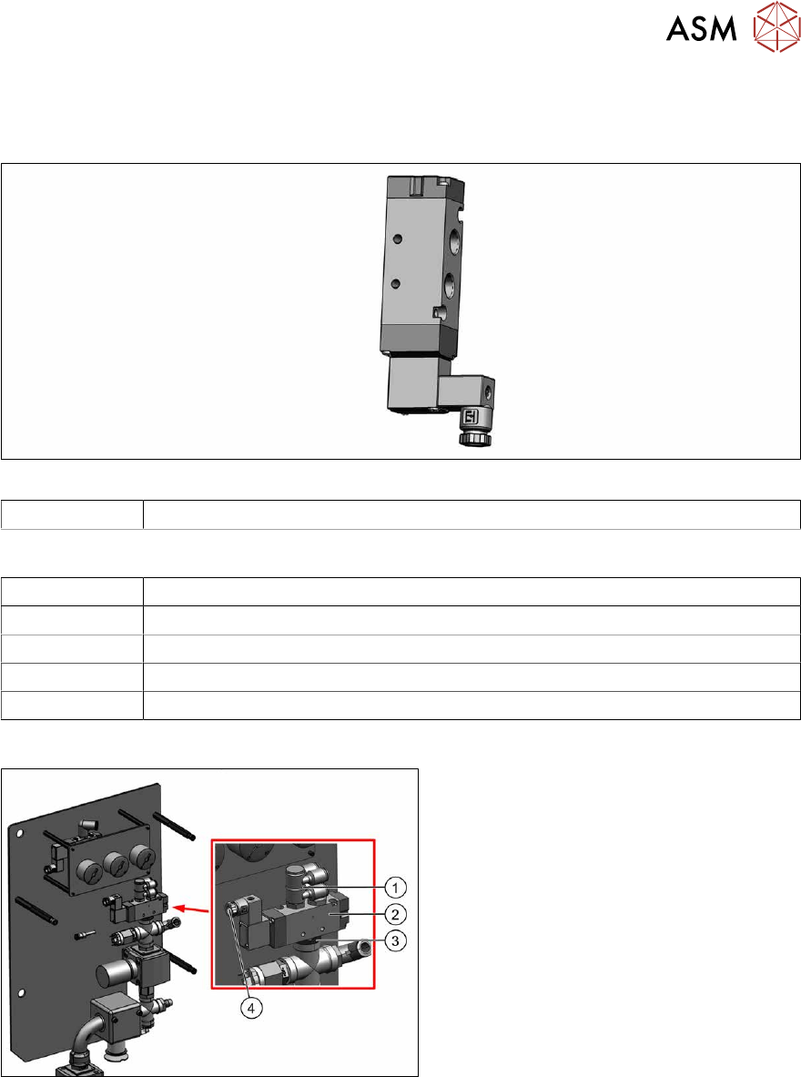
5.7 Replacing the safety valve for the cutters (location 1)
Parts
Fig.107: Safety valve for cutters
00344974-xx Solenoid valve 5/2 G1/4 without manual actuator
Equipment and tools
00353832-xx Allen key set
00096290-xx Fork wrench set
Wire cutters
Cable tie
Sealant (see 5.4 "Sealing the Pneumatic Screwed Connections" [}88])
Overview
Fig.108: Removing the valve
1. Distributor
2. Valve
3. Screwed fixture
4. Electrical connection
5 Pneumatic System
5.7 Replacing the safety valve for the cutters (location 1)
92 Service Manual SIPLACE X-Series S (from Hxxxx) 01/2021
Removal
► Switch off the machine, disconnect it from the power supply and secure it to prevent
unauthorized reactivation.
1.2 "Preparatory work..." [}16]
► Switch off the compressed air supply and then disconnect the machine from the compressed
air supply.
5.2 "Disabling the compressed air supply" [}86]
► To do this, remove the screws fastening the side cover and remove this cover.
5.5 "Dismantling the Lower Side Cover" [}88]
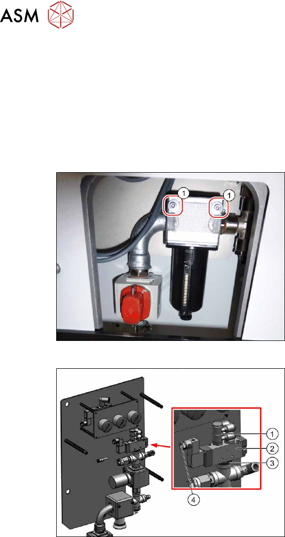
Fig.109: Screws fastening the inlet filter
► Remove the two screws (1) fastening
the inlet filter. This enables you to pull
the whole unit down a little and
provides better access.
Fig.110: Removing the valve
► Unplug the electrical connection(4)
from the valve(2).
► Unplug the pneumatic connections
from the distributor(1)
.
► Remove the screwed connection(3)
from the underside of the valve.
► Carefully remove the valve, together
with the distributor.
► Dismantle the distributor from the
valve.
Installation
Follow the removal instructions in reverse order for installation. Also observe the following instruc-
tions:
► Seal the compressed air system with sealant. Observe the instructions in section 5.4 "Sealing
the Pneumatic Screwed Connections" [}88].