00198829-01_SM_X-Series-S_Hxxxx_EN.pdf - 第96页
5 Pneumatic System 5.9 Replacing the proportional controller (pressure control valve) (location 4) 96 Service Manual SIPLACE X-Series S (from Hxxxx) 01/2021 Fig.117: Proportional controller configurations Configurations…
5 Pneumatic System
5.9 Replacing the proportional controller (pressure control valve) (location 4)
Service Manual SIPLACE X-Series S (from Hxxxx) 01/2021 95
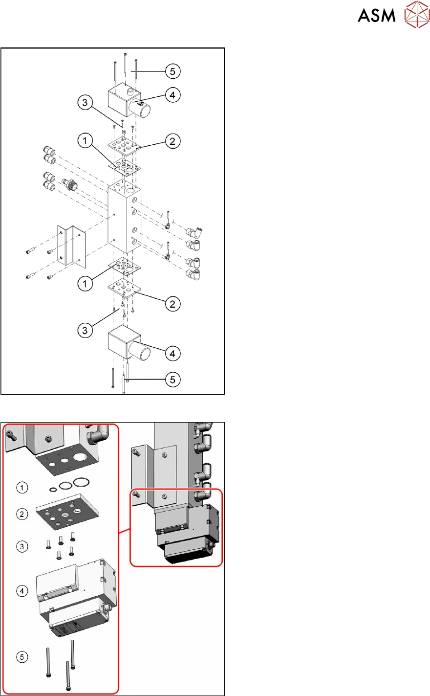
Fig.115: Overview proportional controller (version1)
Version 1:
1. Sealing adapter plate proportional con-
troller [03083211‑xx]
2. Adapter plate proportional controller
3. Fastening screws for adapter plate
Torque: 2.5 – 3.0Nm
4. Proportional controller
5. Fastening screws for proportional con-
troller
Torque: 2.0 – 2.5Nm
Fig.116: Overview proportional controller (version2)
Version 2:
1. 1x O-ring ID10 X 1.0 - NBR70
[03031296‑xx]
1x O-ring ID20 X 1.0 - NBR70
[03146099‑xx]
1x O-ring ID25 X 1.0 - NBR70
[03146100‑xx]
2. Adapter plate bottom [03138952‑xx]
3. 5x ISO10642-M4x14-A2-70
[03091400‑xx]
Torque: 2.5Nm
Loctite 241
4. 1x Proportional controller Sentronic-LP
[03152704‑xx]
5. 3x ISO4762-M4x55-A2-70
[03147182‑xx]
Torque: 2.0 – 2.5Nm
Loctite 241
5 Pneumatic System
5.9 Replacing the proportional controller (pressure control valve) (location 4)
96 Service Manual SIPLACE X-Series S (from Hxxxx) 01/2021
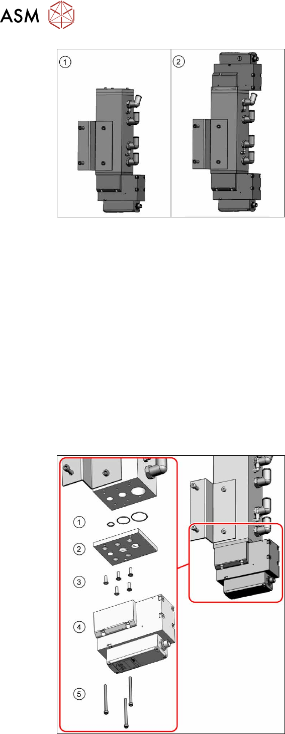
Fig.117: Proportional controller configurations
Configurations
Depending on the configuration, there will be
one or two proportional controllers fitted.
1. One proportional controller (bottom)
Only one proportional controller is fitted,
if the machine is operated exclusively
with SIPLACE C&P20x in vacuum
mode.
2. Two proportional controllers (top and
bottom)
Two proportional controllers are re-
quired in all other cases (mixed head
mode or compressed air mode).
Removal
► Switch off the machine, disconnect it from the power supply and secure it to prevent
unauthorized reactivation.
1.2 "Preparatory work..." [}16]
► Switch off the compressed air supply and then disconnect the machine from the compressed
air supply.
5.2 "Disabling the compressed air supply" [}86]
► To do this, remove the screws fastening the side cover at location 4 and remove this cover.
5.5 "Dismantling the Lower Side Cover" [}88]
► Unplug the electrical connection to the proportional controller.
► Remove the screws fastening the proportional controller and then remove the controller.
Installation
Follow the removal instructions in reverse order for installation. Also observe the following instructions:
► Observe the instructions in section 5.4 "Sealing the Pneumatic Screwed Connections" [}88].
Fig.118: Overview proportional controller (version2)
► Clean the sealing rings(1)and the adap-
ter plate(2)
.
► Lightly grease the sealing rings with
Isoflex Topas NCA52 and insert these
again into the adapter plate.
► Fit the adapter plate with five fastening
screws(3)
(torque: 2.5Nm, Loc-
tite241).
► Fit the proportional controller(4) with
three fastening screws(5)
(torque of
2.0 to 2.5Nm, Loctite241).
5 Pneumatic System
5.10 Replacing the side channel compressor Elmo blower (location 3)
Service Manual SIPLACE X-Series S (from Hxxxx) 01/2021 97
5.10 Replacing the side channel compressor Elmo blower
(location 3)
Parts, equipment and tools
●
Side channel compressor ELMO blower [03004094-xx]
Overview
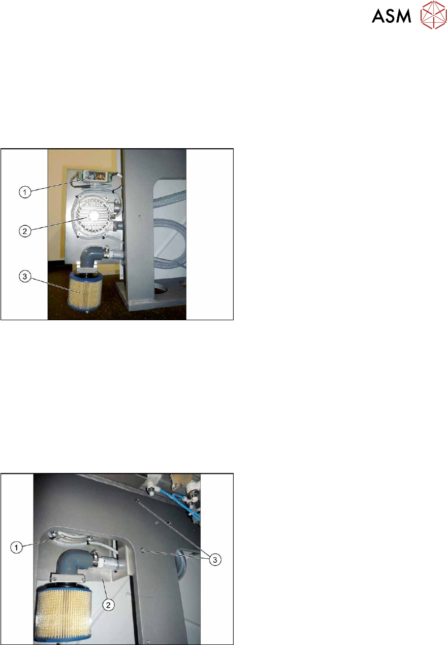
Fig.119: Overview of Elmo blower
1. Elmo blower electronics
2. Elmo blower
3. Cooling air filter
The ELMO blower is located at location 3,
behind the side cover.
Removal
► Switch off the machine, disconnect it from the power supply and secure it to prevent
unauthorized reactivation.
1.2 "Preparatory work..." [}16]
► Switch off the compressed air supply and then disconnect the machine from the compressed
air supply.
5.2 "Disabling the compressed air supply" [}86]
► To do this, remove the screws fastening the side cover and remove this cover.
5.5 "Dismantling the Lower Side Cover" [}88]
Fig.120: Removing the Elmo blower
The Elmo blower (1) and the corresponding
electronics are fitted onto a plate (2)
.
► Remove the two screws (3) fastening
the plate and then carefully pull the
plate out of the machine.
► Unplug all electrical and pneumatic connections to the Elmo blower. You may want to mark
their positions, to make clear assignment easier later on.
► Remove the screws fastening the Elmo blower and then remove it.
Installation
Follow the removal instructions in reverse order for installation.
► Observe the instructions in section 5.4 "Sealing the Pneumatic Screwed Connections" [}88].