Printer 710-810 v9 Covers.pdf - 第14页
COVERS PRINTER COVERS 3.14 Technical Reference Manual Chapter Issue 1 0, Jul 16 Safety Covers Safety covers are fitted to the side pane ls to protect personnel from inadvertent access to the product entry/exit port s. NO…
COVERS
PRINTER COVERS
Chapter Issue 10, Jul 16 Technical Reference Manual 3.13
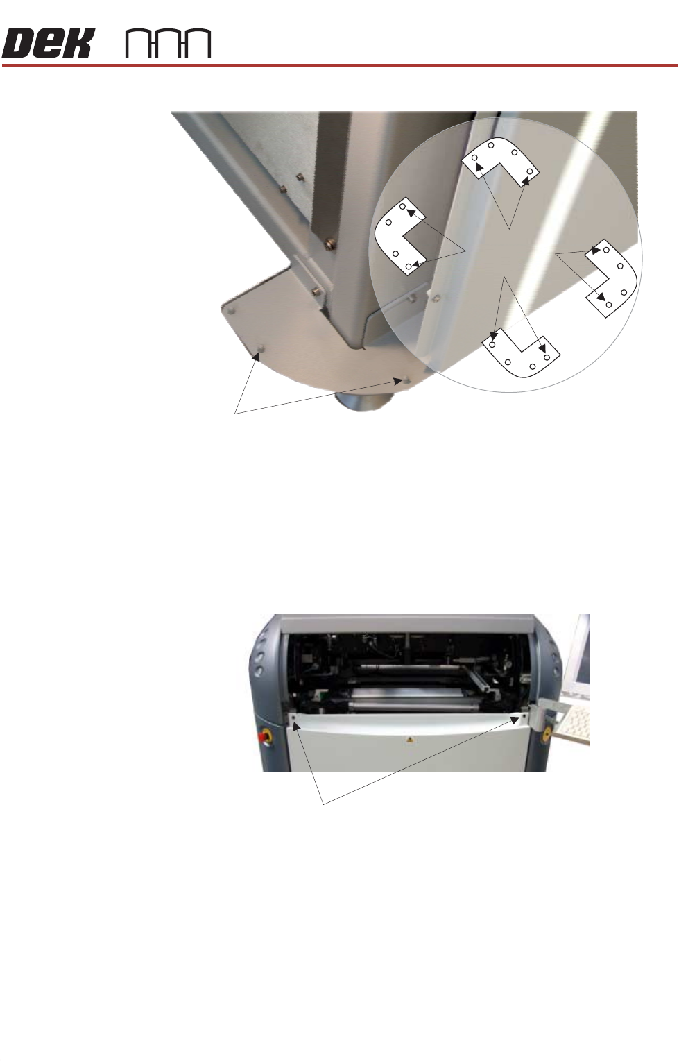
Figure 3-7 Mounting Plates
Front Panel To remove the front panel, carry out the following:
1. Open the sliding cover.
2. Release the two quarter-turn ring fasteners located externally at the top
corners of the panel.
3. Tilt the top of the panel away from the printer and lift the panel clear of the
location pins at the bottom.
Rear Panel To remove the rear panel, carry out the following:
1. Lift the rear printhead cover.
2. Release the two quarter-turn ring fasteners located externally at the top
corners of the panel.
3. Tilt the top of the panel away from the printer and lift the panel clear of the
location pins at the bottom.
Corner Panel
Location Pins
View on Base of Printer
Location Pins
Side, Front &
Rear Panels
Quarter-turn fasteners
COVERS
PRINTER COVERS
3.14 Technical Reference Manual Chapter Issue 10, Jul 16
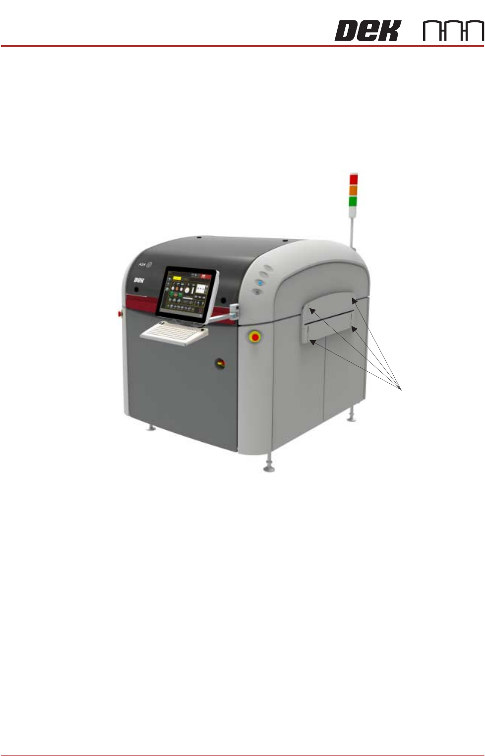
Safety Covers Safety covers are fitted to the side panels to protect personnel from inadvertent
access to the product entry/exit ports.
NOTE
The lower section of the safety panel can be adjusted to accommodate the
thickness of the product.
To remove the safety covers, remove the four securing screws and washers;
remove the cover.
Securing Screws
COVERS
PRINTER COVERS
Chapter Issue 10, Jul 16 Technical Reference Manual 3.15
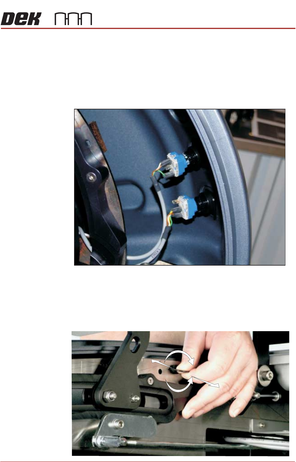
Upper Side Panels To remove an upper side panel, carry out the following:
1. Lift the sliding cover.
2. Lift the rear printhead cover.
3. Remove the safety cover.
4. At the front of the upper side panel, remove the appropriate upper panel
switch contact blocks (System, Jog or Internal light.) The blocks are located
at the rear of the switch bezel.
5. The contact block can be separated from the bezel, (hold the body part to
remove the contact blocks, not the switch wires) by pulling it out of the bezel.
When refitting, the contact body is aligned with the bezel.
6. Release the quarter-turn ring latch fastener, located internally at the top front
of the cover.
Switches (System, Jog)
+
-