Printer 710-810 v9 Covers.pdf - 第2页
COVERS PRINTER COVERS 3.2 Technical Reference Manual C hapter Issue 1 0, Jul 16 Earth Bonding Apart from th e S tyle 3, 4 and 5 covers prin ters, which use me tal covers to make the bond, all external metal surface s are…
COVERS
PRINTER COVERS
Chapter Issue 10, Jul 16 Technical Reference Manual 3.1
CHAPTER 3 COVERS
PRINTER COVERS
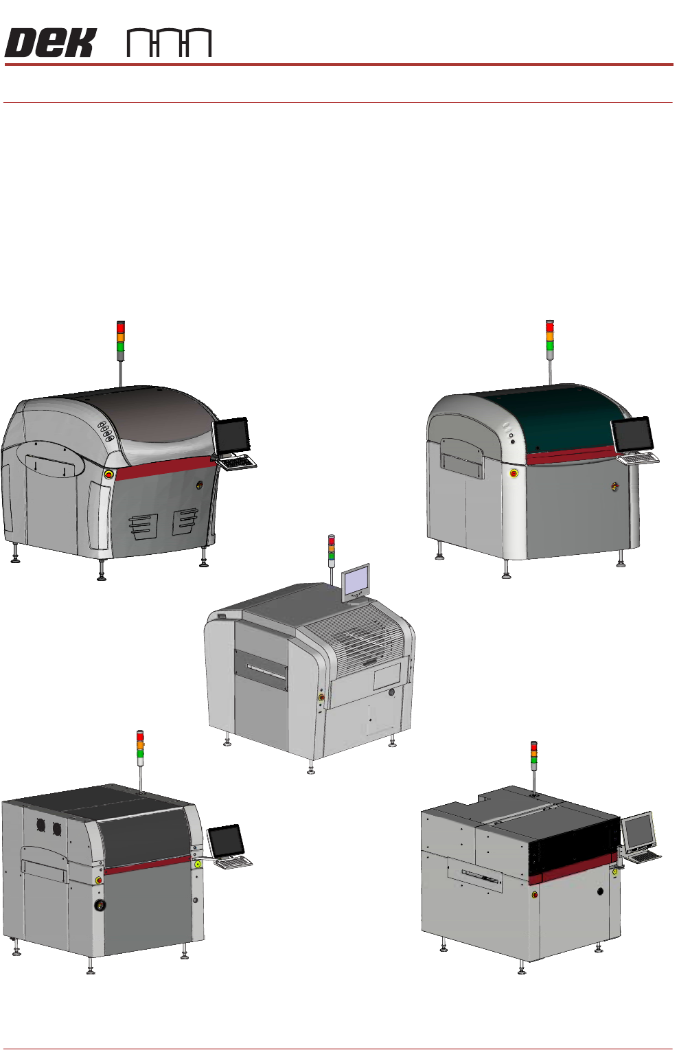
There are five printer cover designs:
• Style 1
• Style 2
• Style 3
• Style 4
• Style 5
Style 2
Style 3
Style 4
Style 1
Style 5
COVERS
PRINTER COVERS
3.2 Technical Reference Manual Chapter Issue 10, Jul 16
Earth Bonding Apart from the Style 3, 4 and 5 covers printers, which use metal covers to make
the bond, all external metal surfaces are mechanically and electrically bonded
to the printer earth point. The bonding wire used is identified by its green and
yellow insulation and is commonly used to earth bond throughout. Care should
be taken when removing these links that they are secured tightly and cleanly,
when replaced.
NOTE
The EPA cover package option is available for the Style 2 Cover machine only.
Its covers are bonded through a series clips and sprung contact studs. The
covers themselves have an electrically conductive conformal coating to dissi-
pate static electricity. For the Electrostatic Protected Area to work effectively, all
fixings are to be kept clean, all panels must be fitted correctly, and the printhead
cover closed.
Safety Interlocks The safety features designed into the machine are for the protection of all
operators and maintenance personnel. ASM strongly recommend safety
devices are never overridden.
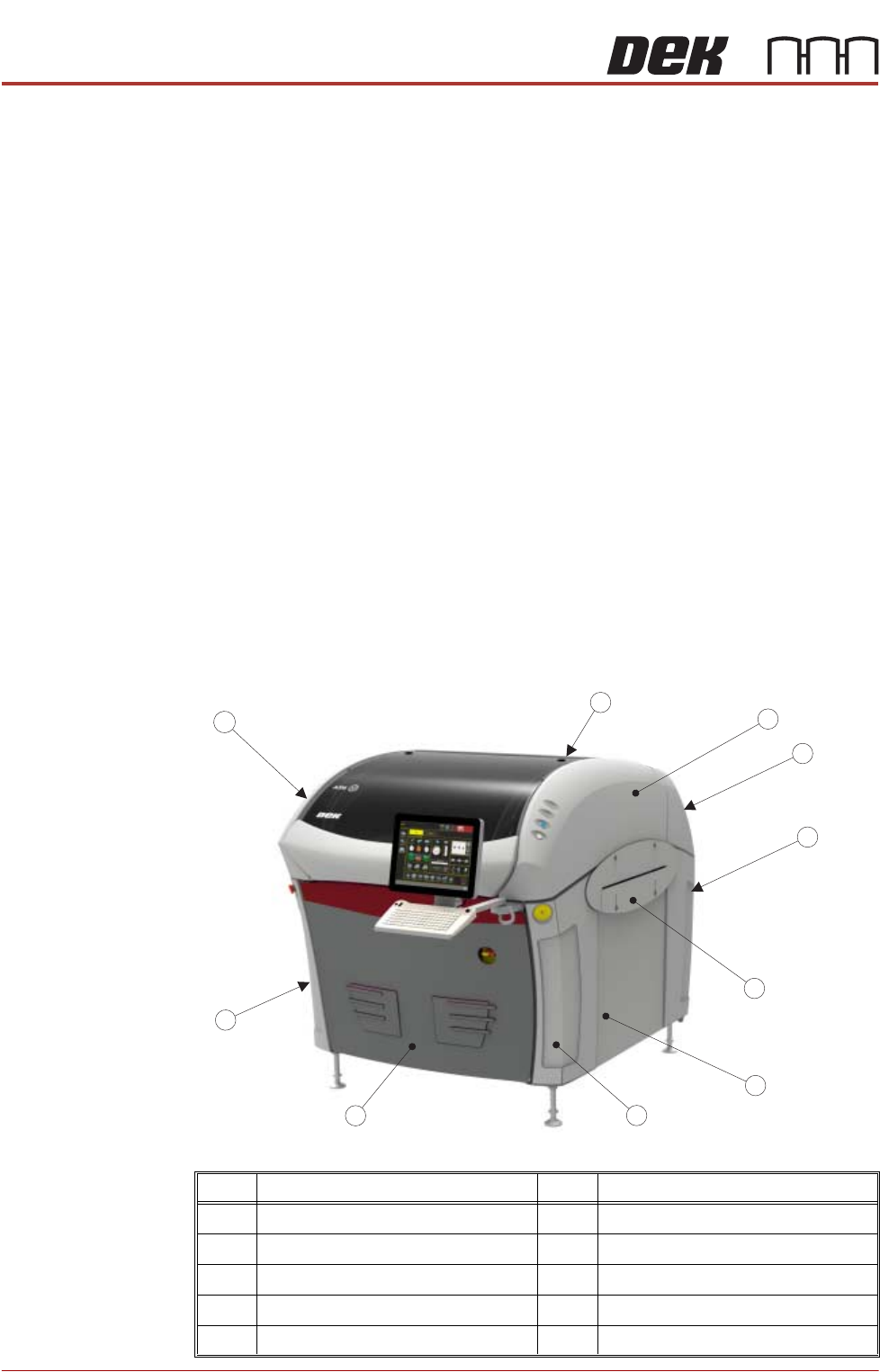
Style 1 Covers In order to protect personnel and prevent damage, eight covers are fitted to the
printer. The upper part of the printer is protected by the sliding printhead cover,
one rear lifting printhead cover and two upper side panels which house the
control switches.
Item Description Item Description
1 Printhead Cover 6 Side Panel (in 2 positions)
2 Right Hand Upper Side Panel 7 Left Hand Front Corner Panel
3 Rear Cover 8 Front Panel
4 Right Hand Lower Side Panel 9 Left Hand Lower Corner Panel
5 Safety Cover (in 2 positions) 10 Left Hand Upper Side Panel
1
2
3
4
5
6
7
8
9
10
COVERS
PRINTER COVERS
Chapter Issue 10, Jul 16 Technical Reference Manual 3.3
NOTE
Some of the covers can only be removed in a specific order due to the covers
interlocking with each other.
Cover Removal Before removing covers ensure that the supplies (air and electrical) have been
isolated from the printer.
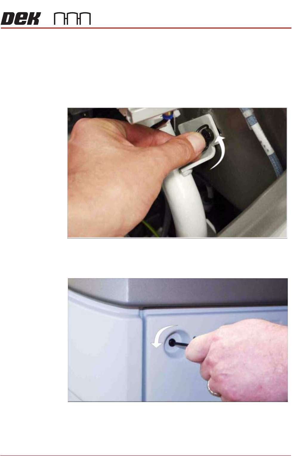
Ring Head Quarter-
Turn Fasteners
To remove a panel secured with ring head quarter-turn fasteners, turn the
fastener anti-clockwise by a quarter-turn and pull out.
Figure 3-1 Ring Head Quarter-Turn Fastener
Button Head
Quarter-Turn
Fasteners
To remove a panel secured with button head quarter-turn fasteners, using a
4mm Allen key, turn the fastener anti-clockwise by a quarter-turn and pull out.
Figure 3-2 Button Head Quarter-Turn Fastener