Printer 710-810 v9 Covers.pdf - 第32页
COVERS PRINTER COVERS 3.32 Technical Reference Manual Chapter Issue 1 0, Jul 16 Upper Rear Panel T o remove the upper rear pan el, carry out the following: 1. Using a 4mm Allen key , undo the two captive screws. 2. T ilt…
COVERS
PRINTER COVERS
Chapter Issue 10, Jul 16 Technical Reference Manual 3.31
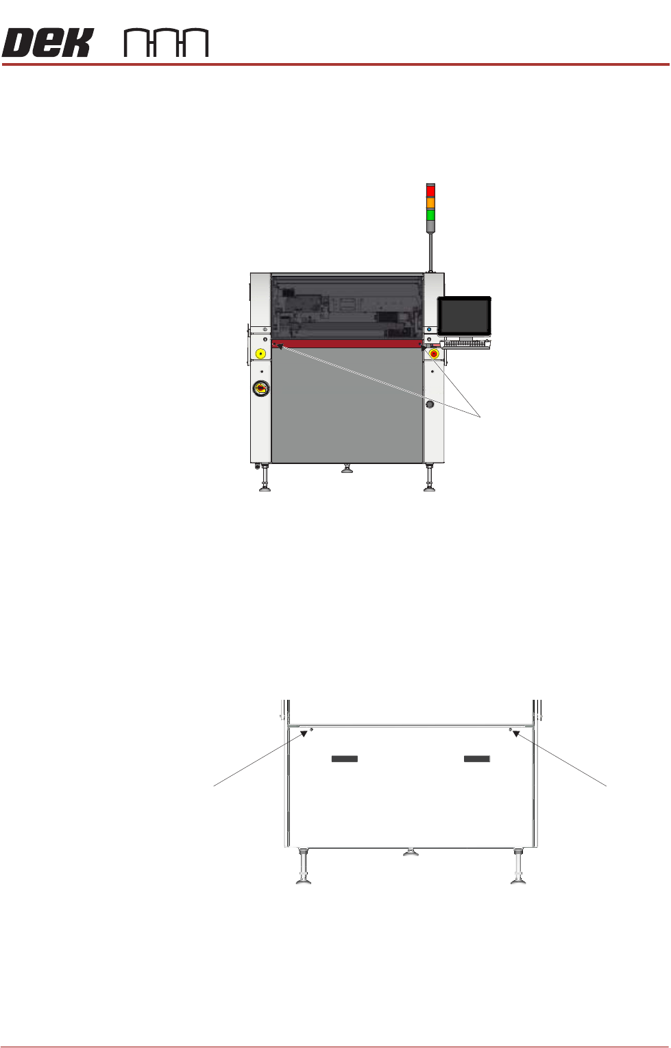
Front Panel To remove the front panel, carry out the following:
1. Open the front printhead cover.
2. Using a 4mm Allen key, undo the two captive screws on the front side of the
panel.
3. Tilt the top of the panel away from the machine and lift the panel clear of the
location pins that locate the panel to the printer frame, taking care not to
damage the earth cable.
Lower Rear Panel To remove the lower rear panel, carry out the following:
1. Using a 4mm Allen key, undo the two captive screws.
2. Tilt the top of the panel away from the machine and lift the panel clear of the
location pins that locate the panel to the printer frame, taking care not to
damage the earth cable.
M5 Captive Screws
View on Front of Machine
M5 Captive Screw
View on Rear of Machine
M5 Captive Screw
COVERS
PRINTER COVERS
3.32 Technical Reference Manual Chapter Issue 10, Jul 16
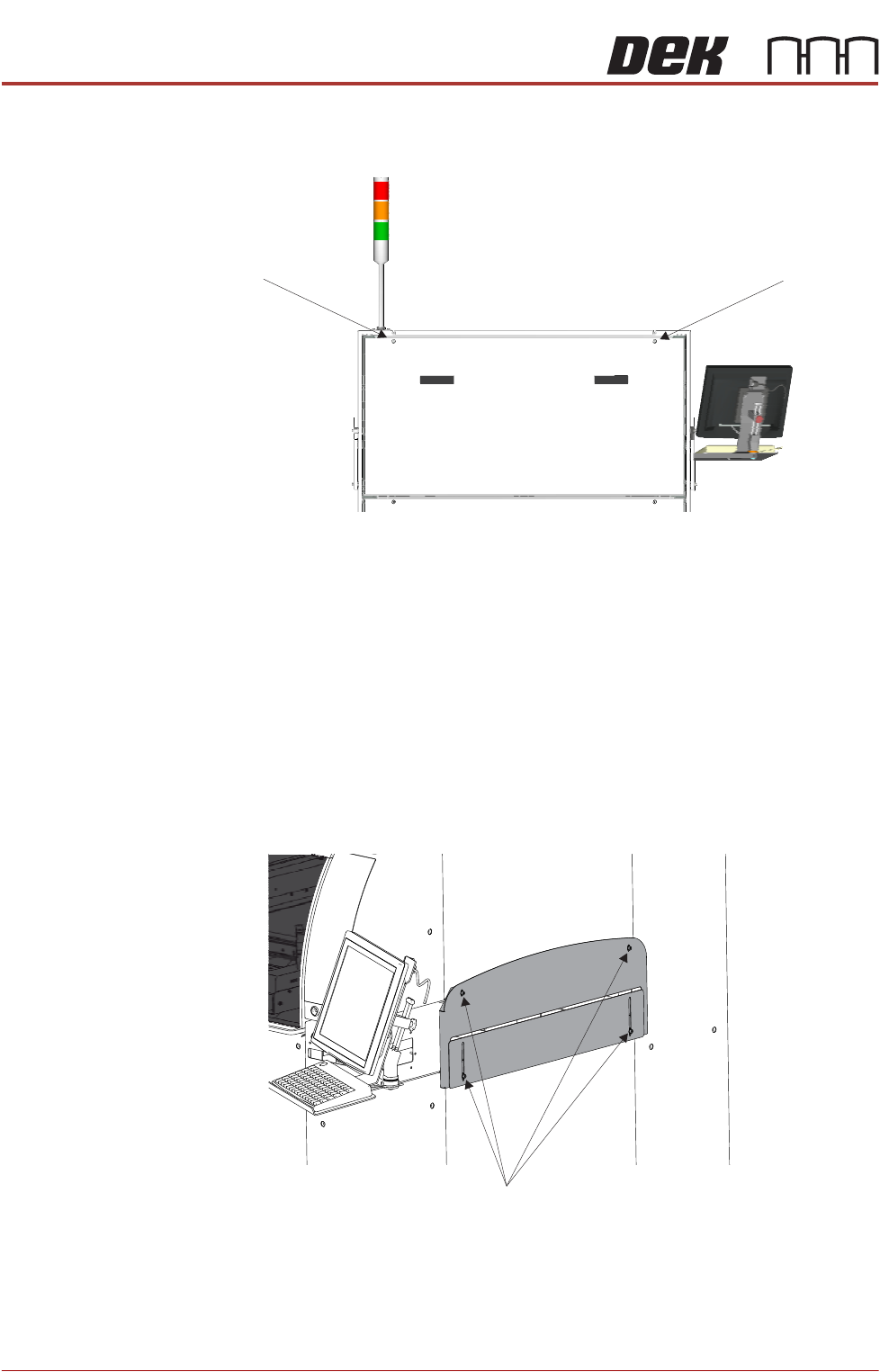
Upper Rear Panel To remove the upper rear panel, carry out the following:
1. Using a 4mm Allen key, undo the two captive screws.
2. Tilt the top of the panel away from the machine and lift the panel clear of the
location pins that locate the panel to the printer frame, taking care not to
damage the earth cable.
Safety Covers Safety covers are fitted to the side panels to protect personnel from inadvertent
access to the board entry/exit ports.
NOTE
The lower section of the safety panel can be adjusted to accommodate the
thickness of the product.
To remove the safety cover, remove the four securing screws.
Rear Corner Panels To remove the rear corner panels, carry out the following:
1. Remove the Left Hand Safety Cover (as detailed previously).
2. Remove the Right Hand Safety Cover (as detailed previously).
M5 Captive Screw
View on Rear of Machine
M5 Captive Screw
Safety Cover Securing Screws
COVERS
PRINTER COVERS
Chapter Issue 10, Jul 16 Technical Reference Manual 3.33
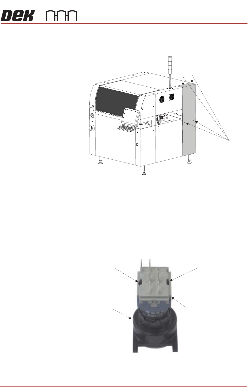
3. Using a 4mm Allen key, undo the appropriate four captive screws.
4. Lift the panel clear of the location pins that locate the panel to the printer
frame, taking care not to damage the earth cable.
5. Repeat Steps 3 and 4 for the other rear corner panel, if required.
Upper Front Corner
Panels
To remove the upper front corner panels, carry out the following:
1. Open the front printhead cover.
NOTE
1. Before a front corner panel can be removed, the control switches (jog
switch and system switch) must be disconnected.
2. Before removing the upper front corner panel, disconnect the connector
for the printhead safety switch.
2. To disconnect the system switch and jog buttons carry out the following:
Front Right Quarter View
Captive Screws
Contact AssemblySwitch Body
Release SlotRelease Slot
View on Rear of Switch