96722_AX-201 AX-301 AX501 Spec bookl - 第13页
3.5 Component alignment 3.5.1 Laser alignment 3.5.2 Vision alignment 3.5.2.1 Component vision alignment Figure 5 Features 11 of 34 Component alignment is used for the alignment of components on leads, edges or bumps, pri…
Placement Head Placement Head Placement Head Placement Head
Single Vision Laser Vision Dual Vision High Accuracy
Maximum stroke 27mm 27mm 40mm 77mm
Placement force Programmable Programmable Programmable Programmable
between 1.5 - 8N between 1.5 - 8N between 2 - 8N between 0.9- 40N
in 0.1N steps
*1
in 0.1N steps
*1
in 0.1N steps in 0.1N steps
*1
Lower forces down
to 0.06N with
restrictions
Variable through Not applicable Not applicable Not applicable Programmable
hole check between 4 and
14 N
Configured in One One Two (four heads Two heads
set of: in total) in total
Toolbits Nozzles Nozzles Nozzles Nozzles and
grippers
*1 Depending on nozzle type
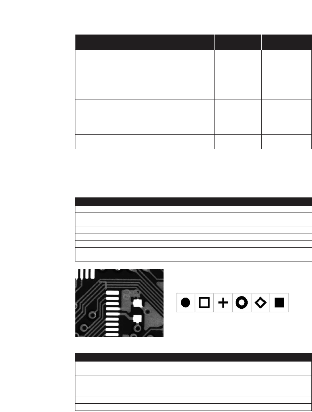
The board alignment camera is used for fiducial and artwork alignment, and is also
used for badmark sensing, position detection of feeder trolleys, toolbit exchange unit,
dump bin and the component vision camera.
Board alignment camera
Camera Field of View 8.6 x 6.8mm
Camera pixels 1024 x 768
Camera pixel resolution 8.4 µm
Illumination Bright field & dark field
Fiducial types All regular types with a contrast level of >30%
Fiducial shape size Fiducial shape size >0.3mm, <3.0 mm
Free zone around fiducial No features allowed within 0.1mm, no look-a-likes
within 2.6mm from fiducial
Examples of artwork and typical fiducials
Badmark sensing
Bad mark type Black or white dot, or fiducial shape
Size >φ 1mm
Color Bad marks can be dark in a light background or light in
a dark background
Contrast At least 30 %
Badmark levels 3
Number of bad marks <2048
per board
3.4 Board
alignment
Figure 4
Features
10 of 34
3.5 Component
alignment
3.5.1 Laser
alignment
3.5.2 Vision
alignment
3.5.2.1 Component
vision
alignment
Figure 5
Features
11 of 34
Component alignment is used for the alignment of components on leads, edges or
bumps, prior to placement on the board. Depending on the configuration of the
machine there are four alignment options available.
The component laser module is part of the Placement Head Laser Vision. The
component laser module is used for component presence check, component
alignment, toolbit type identification and toolbit verification.
Laser alignment
Component size 0.4 x 0.2mm (01005) to 17.5 x 17.5mm
(max diagonal 24.75mm)
Length & width including leads
Height: 10.5mm and higher with restrictions
Min. component thickness 0.130mm
The Component Vision (CV) system is used for the alignment of components on
leads, edges or bumps. Component Alignment is achieved by moving the
component above the lens of an upward-facing digital camera. A combination of
multiple light sources (dark- ,mid-, and bright field illumination and for LFOV also
back light illumination) ensure sufficient contrast between the component (leads)
and the background. Utilizing these light sources the A-Series are capable of
aligning a large range of components. The illumination intensity is automatically
chosen based upon the reflectivity of the respective components. The CV camera
determines the position of the component with respect to a reference plate. The
deviations, together with the fiducial alignment values, will be used to determine the
correct placement position.
There are three component vision modules available for the A-Series.
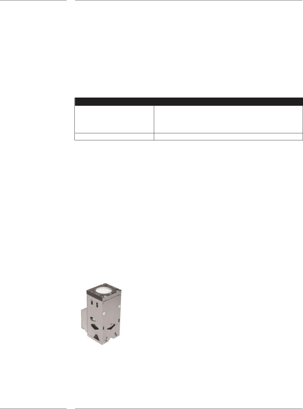
The Component Vision Camera holds one upward looking camera and can inspect
a single component up to 45 x 45mm in one view. Components with bumps down
to 300 micron with a 500 micron pitch can be measured.
AX Component Vision camera
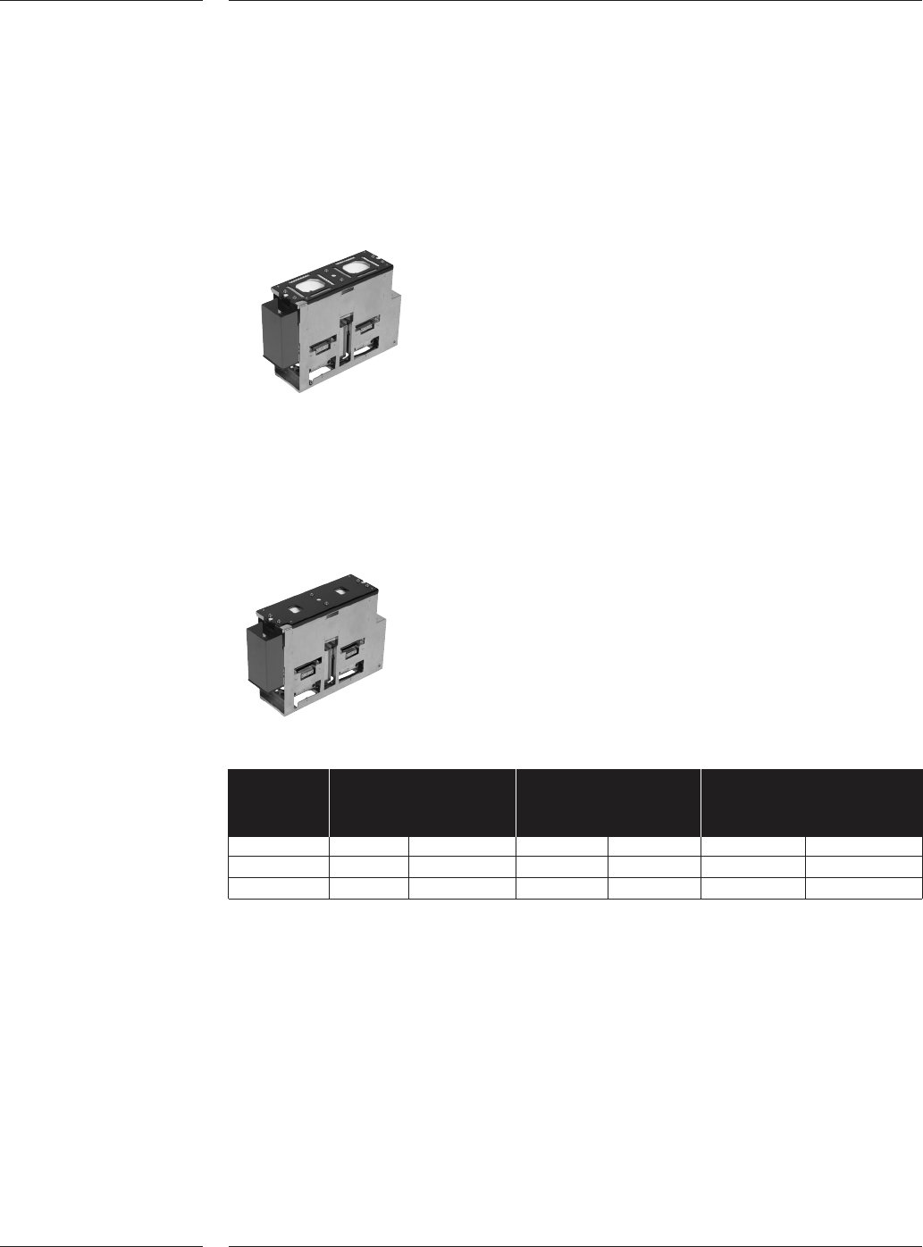
LFOV is holding two upward looking cameras. It is used to align and inspect a wide
range of components up to 45 x 45 mm or 66 x 23 mm with bump or lead width
down to 150 micron. The maximum component size for components picked with
the Placement Head Dual Vision is 21 x 21 mm as four components can be
inspected at the same time. Components up to 165 x 45mm can be measured with
restrictions.
LFOV
SFOV is also holding two upward looking cameras and is used for ultra fine pitch
components like CSPs and flip chips. By use of a smaller field of view (22x22mm)
a higher accuracy can be achieved. The SFOV can be used with the Placement
Head High Accuracy and can align two components at the same time.
SFOV
Camera Maximum Lead Bump
component size
*1
X-axis Y-axis Width Pitch Size Pitch
CV CAMERA 45 45 0.200 0.400 0.300
*2
0.500
*2
LFOV 45 45 0.150 0.300 0.150 0.300
SFOV 22 22 0.080 0.160 0.080 0.160
Note: Component and lead dimensions above or below the noted specification require
an application review.
*1
: Components larger than the noted size can be processed. The CV LFOV can measure
a 165mm long connector, however some restrictions may apply. Also components of
66x23mm (or 23x66mm) can be measured in one view using the Placement Head
High Accuracy.
*2
: For components < 12x12mm, minimum bump size can be 0.150, the minimum pitch
can be 0.300
3.5.2.2 Component
vision Large
Field of View
camera
Figure 6
3.5.2.3 Component
vision Small
Field of View
camera
Figure 7
Features
12 of 34