96722_AX-201 AX-301 AX501 Spec bookl - 第18页
A-Series feeder trolley and bank Feeder # of feeding positions AX-501 AX-301 AX-201 TBF 200~260 120-156 - TTF 220-260 132-156 200 ~ 212 ITF08 100-130 60-78 100 ~ 106 ITF12SV 100-130 60-78 100 ~ 106 ITF12 80-90 48-54 72 ~…

Twin tape feeder, intelligent tape feeder and twin bulk feeder
Feeder Tape Pocket depth Reels Pitch support
width
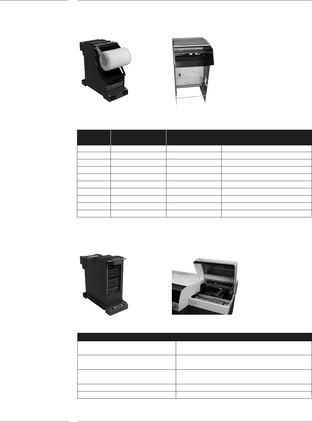
TTF 8mm 3.5mm 7" - 13" 2,4
ITF 8mm 12mm 7" - 13" 2 ~ 56
15" optional
ITF 12mm SV 12mm 12mm 15" 2 ~ 56
ITF2 12mm 12mm 12mm 7" - 13" 2 ~ 56
15" optional
ITF2 16mm 16mm 12mm, 7" - 13", 2 ~ 56
15.4mm optional 15" optional
ITF2 24mm 24mm 12mm, 7" - 13", 2 ~ 56
16.5mm optional 15" and 22" optional
ITF2 32mm 32mm 12mm, 7" - 15", 2 ~ 56
16.5mm optional 15" and 22" optional
ITF2 44mm 44mm 12mm, 7" - 15", 2 ~ 56
16.5mm optional
ITF2 56mm 56mm 16.5mm, 7" - 15", 2 ~ 56
optional 22" optional
72mm Prec. Pro 72mm 18mm 7" - 15" 2 ~ 48
Univ. feeder
Component EIA Lanes EIA Component specifications
description Length (mm) Width (mm) Thickness
C0201 2 0.57 ~ 0.63 0.27 ~ 0.33 0.27 ~ 0.33
C0402 2 0.95 ~ 1.05 0.45 ~ 0.55 0.45 ~ 0.55
R0402 2 0.95 ~ 1.05 0.45 ~ 0.55 0.30 ~ 0.40
C0603 2 1.53 ~ 1.67 0.73 ~ 0.87 0.73 ~ 0.87
R0603 2 1.50 ~ 1.70 0.70 ~ 0.90 0.35 ~ 0.55
MELF R0604 2 1.50 ~ 1.70 Ø 0.90 ~ Ø 1.10
C0805T0.6 2 1.90 ~ 2.10 1.15 ~ 1.35 0.50 ~ 0.70
C0805T1.25 1 1.90 ~ 2.10 1.15 ~ 1.35 1.15 ~ 1.35
R0805 2 1.90 ~ 2.10 1.15 ~ 1.35 0.50 ~ 0.70
MELF R0805 1 1.90 ~ 2.10 Ø 1.15 - Ø 1.35
Please refer to the Compatibility matrix on page 31 for an overview of other compatible
feeders and their machine relationship.
4.2 Feeding
4.2.1 Specifications
Intelligent tape
feeders & Twin
tape feeders
Figure 11
4.2.2 Specifications
Bulk feeders
Options
15 of 34
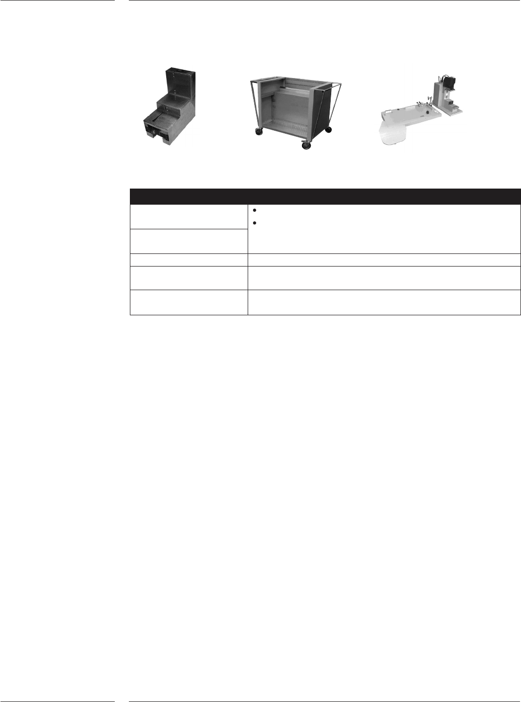
A-Series feeder trolley and bank
Feeder # of feeding positions
AX-501 AX-301 AX-201
TBF 200~260 120-156 -
TTF 220-260 132-156 200 ~ 212
ITF08 100-130 60-78 100 ~ 106
ITF12SV 100-130 60-78 100 ~ 106
ITF12 80-90 48-54 72 ~ 74
ITF16 80-90 48-54 68 ~ 72
ITF24 60 36 50 ~ 52
ITF32 40-50 24-30 40
ITF44 40 24 30 ~ 32
ITF56 25-30 15-18 24
Note: Maximum quantity of feeders depend on robot configurations. In the AX-201, the
largest figure represents the # of feeder positions PH-DV, the smaller figure represents the
# of feeder positions using PH-HA.
A-Series tray trolley and AX Extension Module
Tray trolley
Supported tray type JEDEC-95-1. OEC 60286-5 or 327 x 274mm or
338 x 240mm
Number of tray carriers for tray height 47
up to 8 mm
Number of tray carriers for tray height 23
between 8mm and 13 mm
Maximum Tray load 0.6 kg
Feeder slots 1 feeding section
Note: AX Extension Module (under development) is required for tray feeding on AX-501/301
4.2.3 Feeder
trolleys &
banks
Figure 12
4.2.4 Tray
trolley
Figure 13
Options
16 of 34
The following feeder options support the TTF and all ITF2 feeders. TLU, Feeder storage
card and ITF-TTF analysis and calibration tool
Description
ITF-TTF Analysis tool Fast feeder analysis and trouble shooting
Easy operation by local technical personnel
Quick feeder repair for fast return to operation
ITF-TTF Calibration tool
ITF Tape loading unit For off-line loading of tapes. Capacity of one (1) tape feeder
Feeder storage cart 50 x 8mm feeders (or equivalent)
100 reels 8mm size
Small feeder storage cart 20 x 8mm feeders (or equivalent)
40 reels 8mm size
Each machine is supplied with one user interface at the front-right-hand side. A
2
nd
user interface can be optionally mounted at the front-left-hand side. If rear
side feeding is configured a 2
nd
user interface will be mounted on the rear side of
the machine.
The re-use module is available for components, which fail inspection because of
pick-up errors or vision alignment. The required reject position can be
programmed by the user and specified per component.
For the AX-201 an accuracy verification set can be used to verify the accuracy of
the placement system by means of a glass board and glass components. The
machine places the glass components and measures the accuracy using the
board alignment camera. The components are placed under four different angles,
and the user can define how many placements should be done. Offset measure-
ments are automatically calculated and can be used to improve the calibration
file. This verification set is required to reach the best possible accuracy.
The A-Series off line vision tool is available for off line preparation and inspection
of components. This means that time spent on the machine for product change
over, with new components, can be minimized. This tool, consisting of a Large
Field Of View camera with toolbit interface, an industrial PC and monitor, is a
simulation model of an AX. Compressed air is required to operate this tool.
4.2.5 Other
feeding
options
Figure 14
4.3 2
nd
User
interface
4.4 Re-use
module
4.5 Accuracy
verification
set
4.6 A-Series
vision tool
Options
17 of 34