444CEMM2(CM201).pdf - 第24页
Page 2-24 Procedures of Machine Parameter T eaching 2-2-3 Chip Recognition Camera θ θ θ θ θ -axis Origin Offset 1. Press . 2. Select the table for teaching. 3. Press UNLOCK + Jig setting . • The head moves to the feeder …
Page 2-23
MACHINE PARAMETER
2
2
2
Procedures of Machine Parameter Teaching
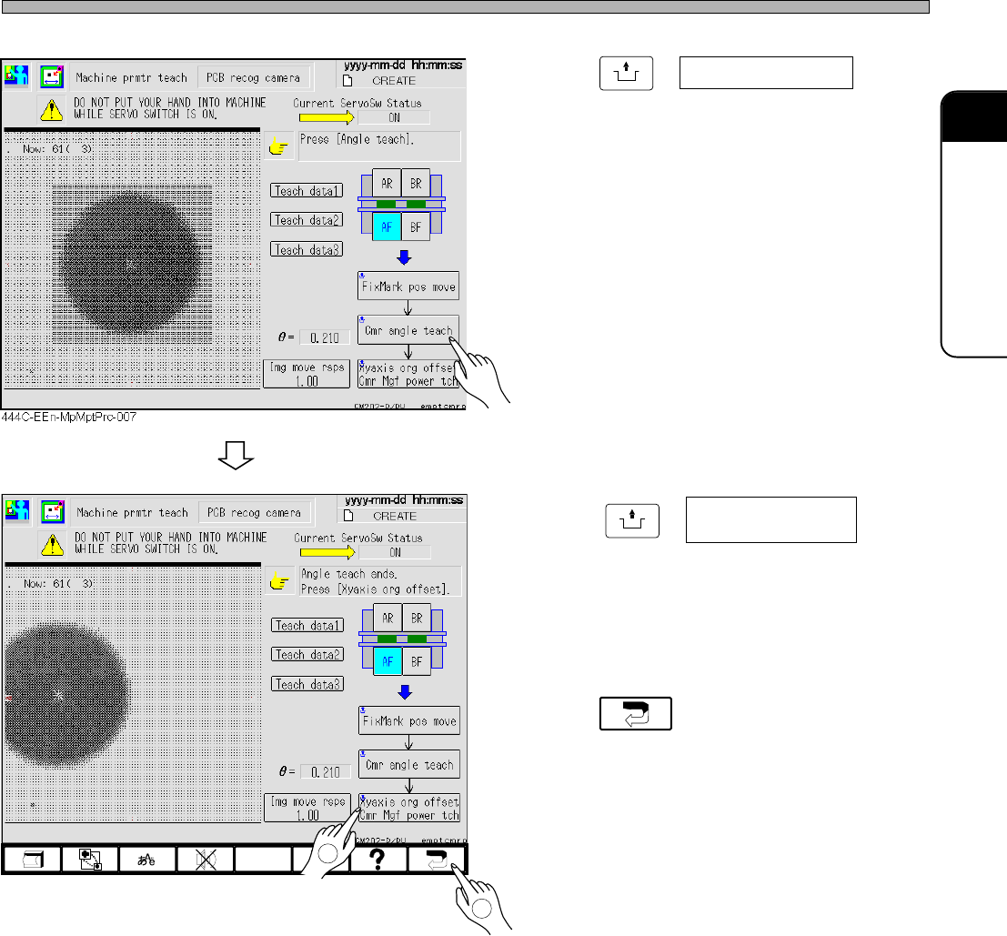
5. Press
UNLOCK
+ Cmr angle teach .
• Deviation in
θ
direction for setting the head
camera (rotation around Z-axis)
∗ When the deviation is over the tolerant value,
the message appears and the machine stops.
6. Press
UNLOCK
+ .
• Teaching for the pixel rate of the head camera
and the origin of the X- and Y-axis are carried
out.
7. Press .
• The “Machine prmtr teach menu” screen
reappears.
Xy axis org offset
Cmr Mgf power tch
444C-E-MMA02-A03-05
444C-EEn-MpMptPrc-008
2
1
Page 2-24
Procedures of Machine Parameter Teaching
2-2-3 Chip Recognition Camera
θθ
θθ
θ
-axis Origin Offset
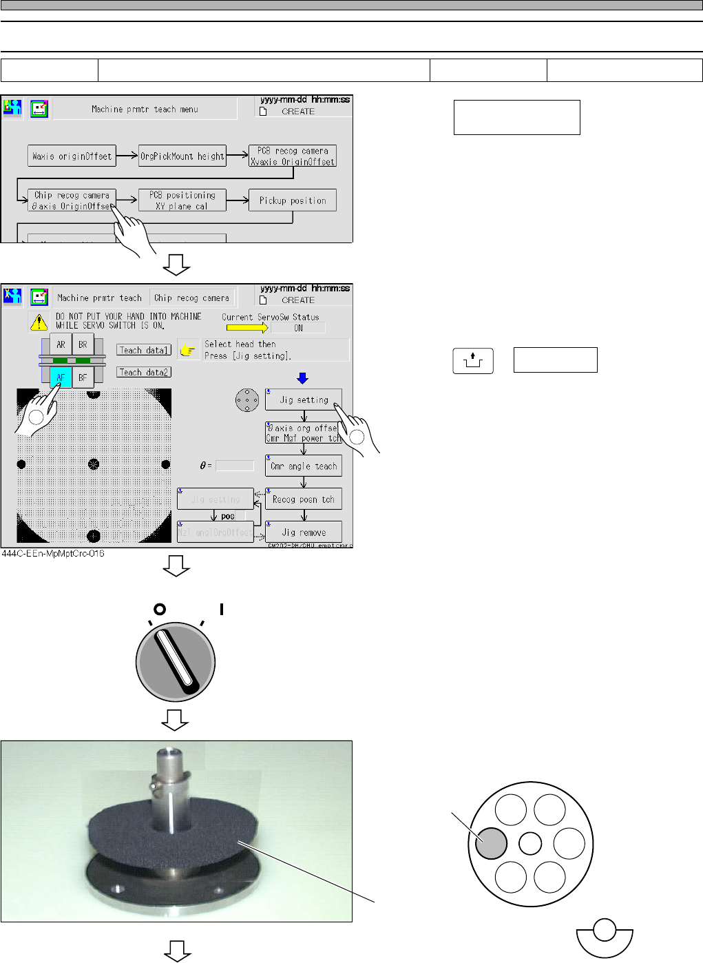
1. Press .
2. Select the table for teaching.
3. Press
UNLOCK
+ Jig setting .
• The head moves to the feeder table.
• After the head has traveled to the jig setting
position, the servo switch turns OFF automati-
cally.
4. Turn OFF the servo switch.
5. Open the safety cover.
6. Set the nozzle jig to pos 3.
To the next page
OFF ( )
ON ( )
SERVO
444C-E-MMA02-A03-06
Tools Required time 5 minutesNozzle jig
pos 3
Nozzle jig
Chip recog camera
θ
axis origin offset
444C-EEn-MpMpt-004
2
1
444C-453P
444C-417E
Page 2-25
MACHINE PARAMETER
2
2
2
Procedures of Machine Parameter Teaching
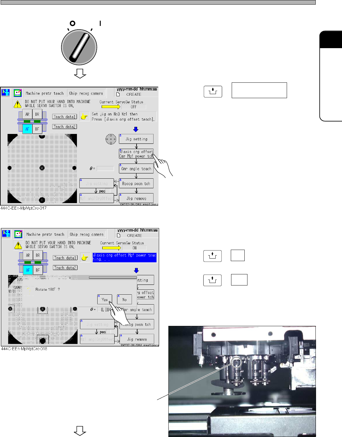
7. Close the safety cover.
8. Turn ON the servo switch.
9. Press
UNLOCK
+ .
10. If the nozzle holder is at the position
as shown on the following picture,
press
UNLOCK
+ No ,
otherwise,
press
UNLOCK
+ Yes .
To the next page
OFF ( )
ON ( )
SERVO
444C-455P
444C-E-MMA02-A03-05
You can see the set screw
θ
axis org offset
Cmr mgf power tch