444CEMM2(CM201).pdf - 第65页
Page 3-25 SOLUTIONS FOR ERROR 3 3 PHI LK2 PH 926 PH 927 PH 920 PH 921 PH 922 PH 923 444C-E-MMA03-A04-03 3-3 Load Arrangement 3-3-1 Load Arrangement of CM202 • The target model is CM202-D/DU/DH/DHU/DK. ( As for the main b…
Page 3-24
3-2-9 Returning from Power Interruptions Occurred during Operation
1. Immediately after power failed
(1) If the power supply to the air compressor and also the air supply have stopped, the nozzle
cylinder in the head may remain extended. Therefore never hand-move the XY beam. Otherwise
the nozzle tip may cause interference and break.
When the air supply is restored, the nozzle cylinder is retracted to the “retraction limit.” The XY
beam should be moved after that.
Reference: Unless the air supply stops, the nozzle cylinder is forcibly retracted to the “retraction
limit” when the machine power is interrupted.
(2) Turn OFF the main power supply switch of the machine temporarily.
2. Immediately after factory power source is restored
(1) Turn ON the main power supply switch of the machine.
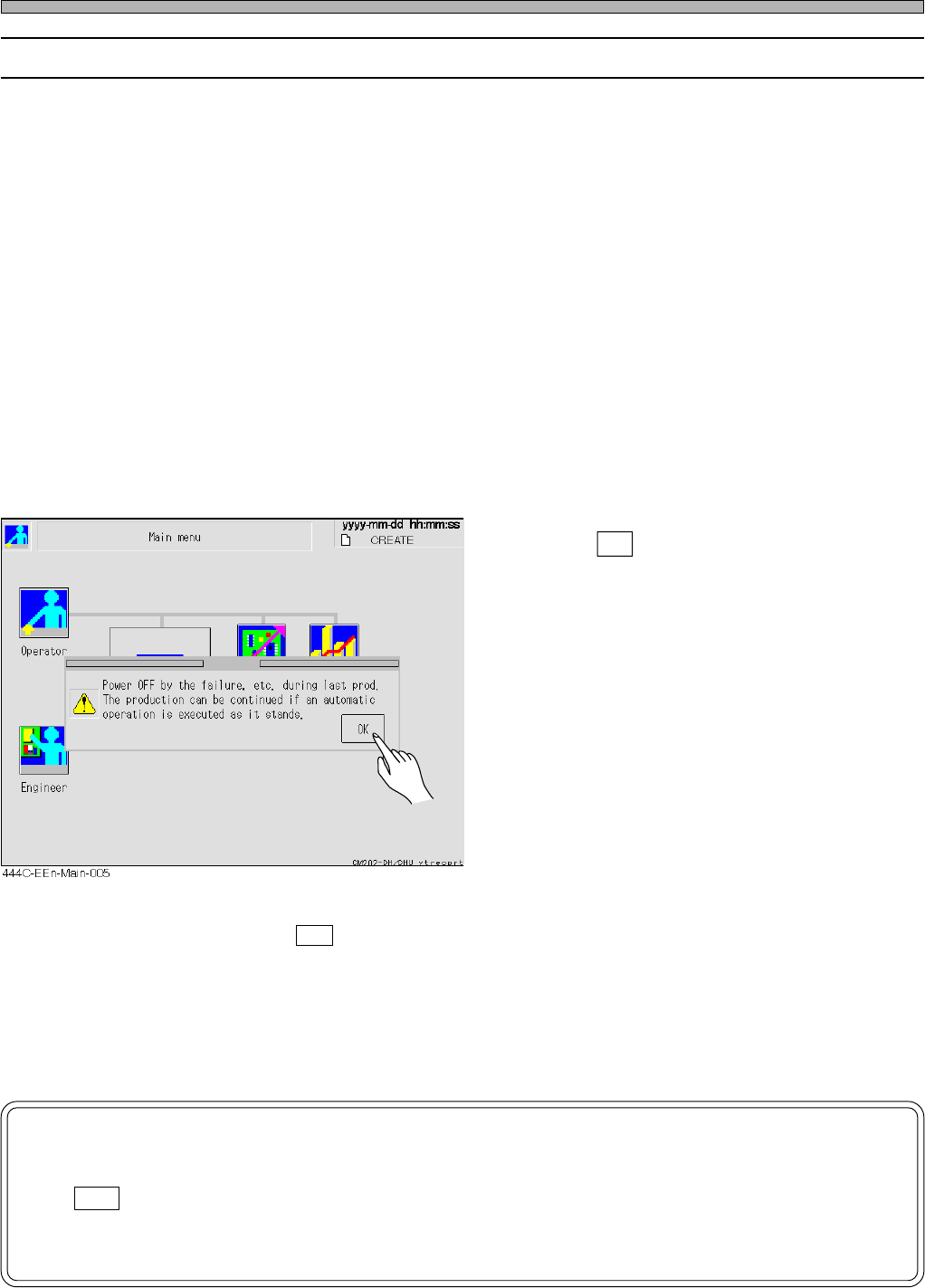
After power-on, the machine system starts up. When [Main menu] screen is displayed, a mes-
sage appears.
• Press OK .
• If it does not appear, an automatic width
adjustment operation is always carried out in
operation because the machine has not
recognized that power failed. Therefore re-
move the boards on the transport conveyor for
the time being.In this case, the continued
mounting is not available. Put the boards again
during a wait for the previous process.
(2) Restart [Production] operation.
When pressing an OK button on the window above, you can continue mounting if performing
[Production] operation immediately without doing anything else. (Also the automatic width adjust-
ment operation is not carried out.) As a result of the continued mounting, however, such as
missing components or double mounting may occur in the production boards. After the mounting,
please make a visual inspection.
NOTICE
If you perform such an operation as [Machine adjust] or [Data modify] after press-
ing OK button in the message “Power OFF by the failure, ..... as it stands.,” the
automatic width adjustment operation is carried out. Therefore remove the boards
on the transport conveyor for the time being.
Check and Solutions
444C-E-MMA03-A03-01
Page 3-25
SOLUTIONS FOR ERROR
3
3
PHI
LK2
PH
926
PH
927
PH
920
PH
921
PH
922
PH
923
444C-E-MMA03-A04-03
3-3 Load Arrangement
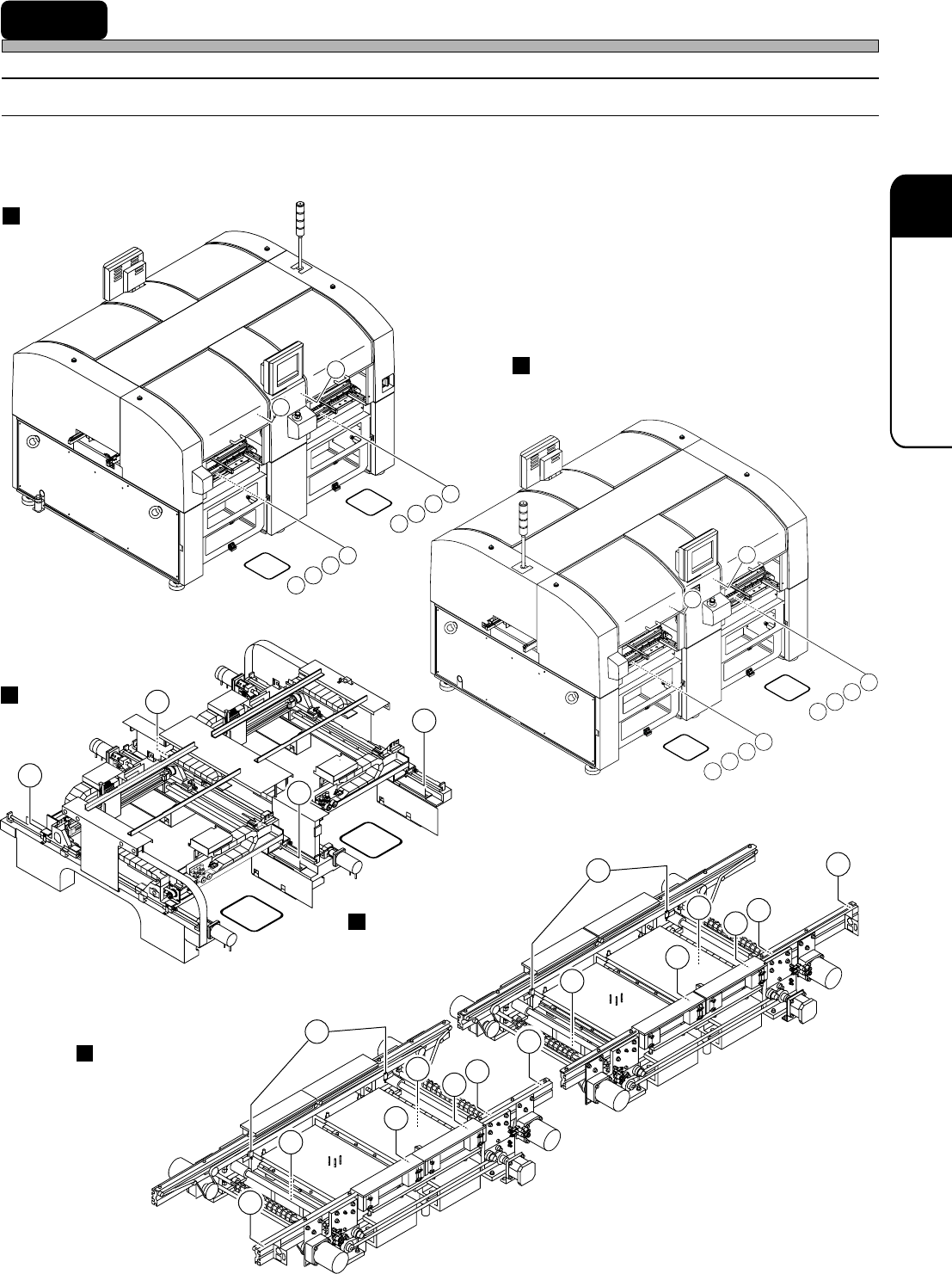
3-3-1 Load Arrangement of CM202
• The target model is CM202-D/DU/DH/DHU/DK.
( As for the main body, the illustrations of the CM202-DH are used.)
Left board conveyor
X-Y unit
SW
930
SW
530
VL
232
VL
233
VL
234
VL
235
VL
B32
VL
B33
VL
B34
VL
B35
H1
H3
VL
D32
VL
D33
VL
D34
VL
D35
VL
432
VL
433
VL
434
VL
435
SW
531
SW
931
H4
H2
H1
H3
PH
A37
PH
137
PH
337
PH
C37
PH
524
PHI
LK1
PH
526
PH
527
PH
520
PH
521
PH
522
PH
523
4U4C-910E
4U4C-911E
444C-433E
444C-436E
444C-437E
Front side of the main body
Rear side of the main body
Right board conveyor
Page 3-26
444C-E-MMA03-A04-01
Load Arrangement
H1 H2 H3 H4
PH
135
PH
G05
PH
G06
PH
335
PH
H05
PH
H06
PH
A35
PH
I05
PH
I06
PH
C35
PH
J05
PH
J06
PH
136
H1
PH
A36
H2
PH
336
H3
PH
C36
H4
H1 H2 H3 H4
H1 H2 H3 H4
LS
B34
LS
D34
LS
434
LS
234
LS
B26
LS
D26
LS
426
LS
226
PH
B27
PH
D27
PH
427
PH
227
LS
B30
LS
D30
LS
430
LS
230
444C-434E
444C-435E
444C-438E
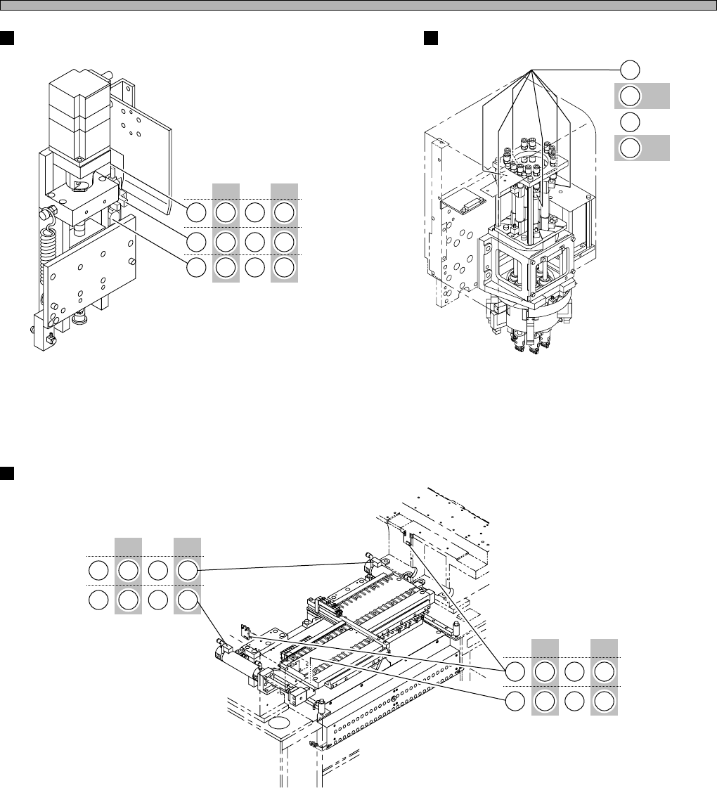
Feeder base
Z unit
Transfer head