M6e_ServiceManual_e.pdf - 第71页
4 Electrical Section 4-5 Electrodes on Feeder / Feeder Bank When electrodes on the feeder bank and the tape feeder get dirty, clean them as follows: NOTE: If the electrodes are touched by hand or have com e into contact …
4 Electrical Section
4-4
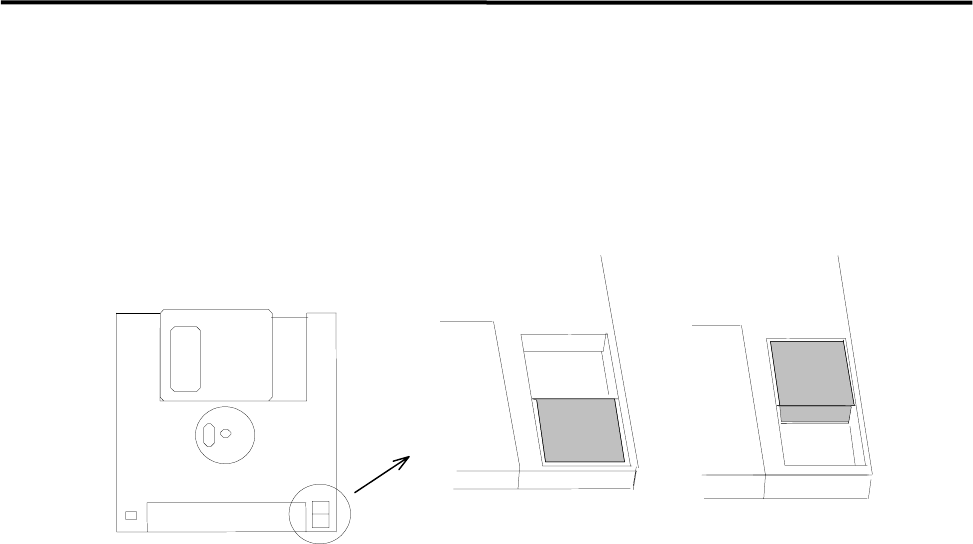
■ Write Protect
To prevent formatting or overwriting data by mistake, floppy disks can be write-protected. Data can be read
from write-protected floppy disks, but cannot be written on them. When you slide the plastic tab to open
the window, the floppy disk is write-protected. When the window is closed, data can be written on the
floppy disk.
Not protectedProtected
Cleaning of Disk Drive
The head of a floppy disk drive gets dirty from repetitive writing and loading. If you continue using it
without any cleaning, malfunctions may occur and it also shortens the life of the floppy disk. Clean monthly
the head of the floppy disk drive with a conventional head cleaner .
4 Electrical Section
4-5
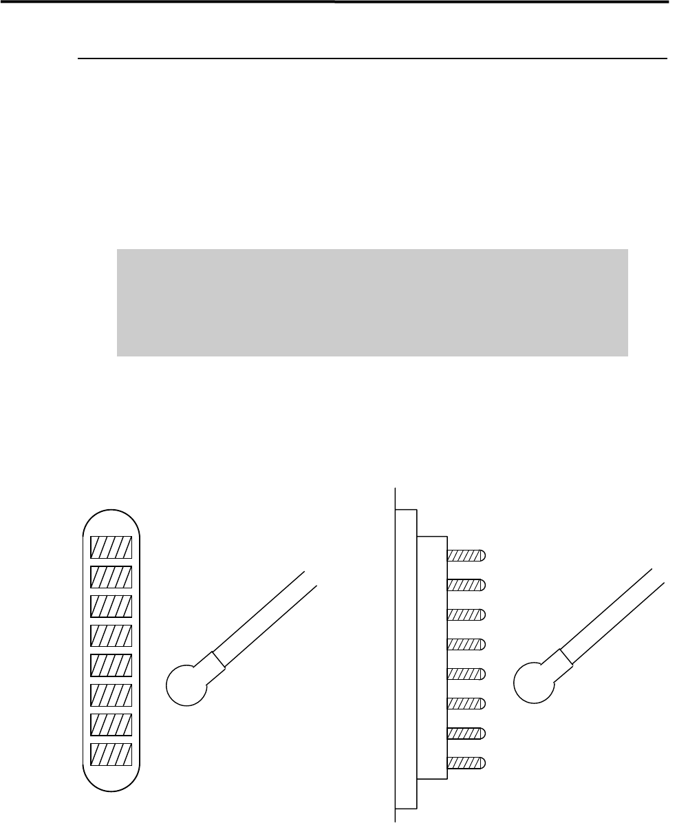
Electrodes on Feeder / Feeder Bank
When electrodes on the feeder bank and the tape feeder get dirty, clean them as follows:
NOTE: If the electrodes are touched by hand or have come into contact with foreign matter, cleaning is
recommended even if no dirt can be observed visually.
ACTION: Clean the electrodes by wiping off dust gently with a dry cotton swab or non-woven fabric. When cleaning
them, check that the pins are not bent. If they are bent excessively, contact i-PULSE for repair. Continuing
to use them if the pins are bent may scratch the contact surface of the feeder bank.
Do not use alcohol, water base detergents and organic solvent, such as
thinner, benzene and acetone.
Do not use sandpaper and tools with sharp blade or edge, such as a knife and
a screwdriver.
NOTE: If they get stubborn stains, try not to get rid of them forcedly. Please contact us.
Cotton swab
Pin Electrodes on feederElectrodes on feeder bank
Cotton swab
4 Electrical Section
4-6
Adjustment of Board Detection Sensors
This section explains how to adjust the sensitivity of the board detection sensors.
● LC6-M90H1-00X PHOTO SENSOR E3Z-D81 (OMRON)
z Entrance sensor
z Exit sensor
z Exit buffer arrival sensor
■ Adjusting Method
① Place a PCB on the conveyor belt in the direction in which PCBs will be placed for actual production
operation.
② Turn the sensor’s sensitivity volume counter-clockwise (toward “min”) as far as it will go, to set the
sensitivity to the minimum level.
*The volume can be turned 3/4 turns. Turning it clockwise (toward “max”) increases the sensitivity
and turning it counter-clockwise (toward “min”) decreases it.
③ With the PCB detected by the sensor, turn the volume clockwise (toward “max”) gradually, up to the
point (A) where the orange LED (operation indicator) begins to light up.
④ Remove the PCB and turn the volume clockwise (toward “max”), up to the point (B) where the orange
LED begins to light up. (If the orange LED does not light up even if the volume is turned clockwise as
far as it will go, the position to which the volume has been turned clockwise as far as it will go will be
considered to be position (B).)
⑤ The center position between the positions (A) and (B) is set as the adjustment position. With the PCB
detected at that position, check that both orange and green LEDs light up at the same time. Also check
that only the green LED lights up when the PCB is removed.
⑥ When the conveyor cover is provided because of the safety spec., attach a black rubber sheet to the
sensor detection position on the bottom of the cover to prevent false detection.
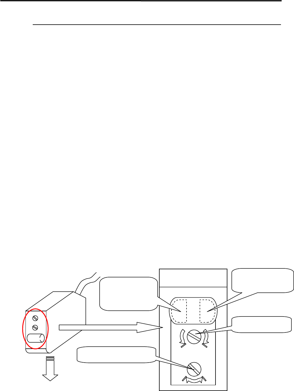
NOTE: Make sure that the operation selector switch is set to “L” (ON when light is entered).
Operation selector switch
Sensitivity volume
Operation-stable
indicator
(Green LED)
Operation indicator
(Orange LED)
Sensor emitting direction
DL
min max
Enlarged View of Sensor
(Shown in upside down
direction)