LBO für minimale LP-Breite 50mm an D4 - 第35页
LBO 50 mm SIPLACE D4 2 Assembly instructions SOKO Stopper LBO for minimum board size 50 mm SIPLACE D4 11/2007 Edition 35 : T ighten the fixing for the guiding shafts easily . : Mount the right cove r of the output convey…
2 Assembly instructions SOKO Stopper LBO for minimum board size 50 mm SIPLACE D4 LBO 50 mm SIPLACE D4
11/2007 Edition
34
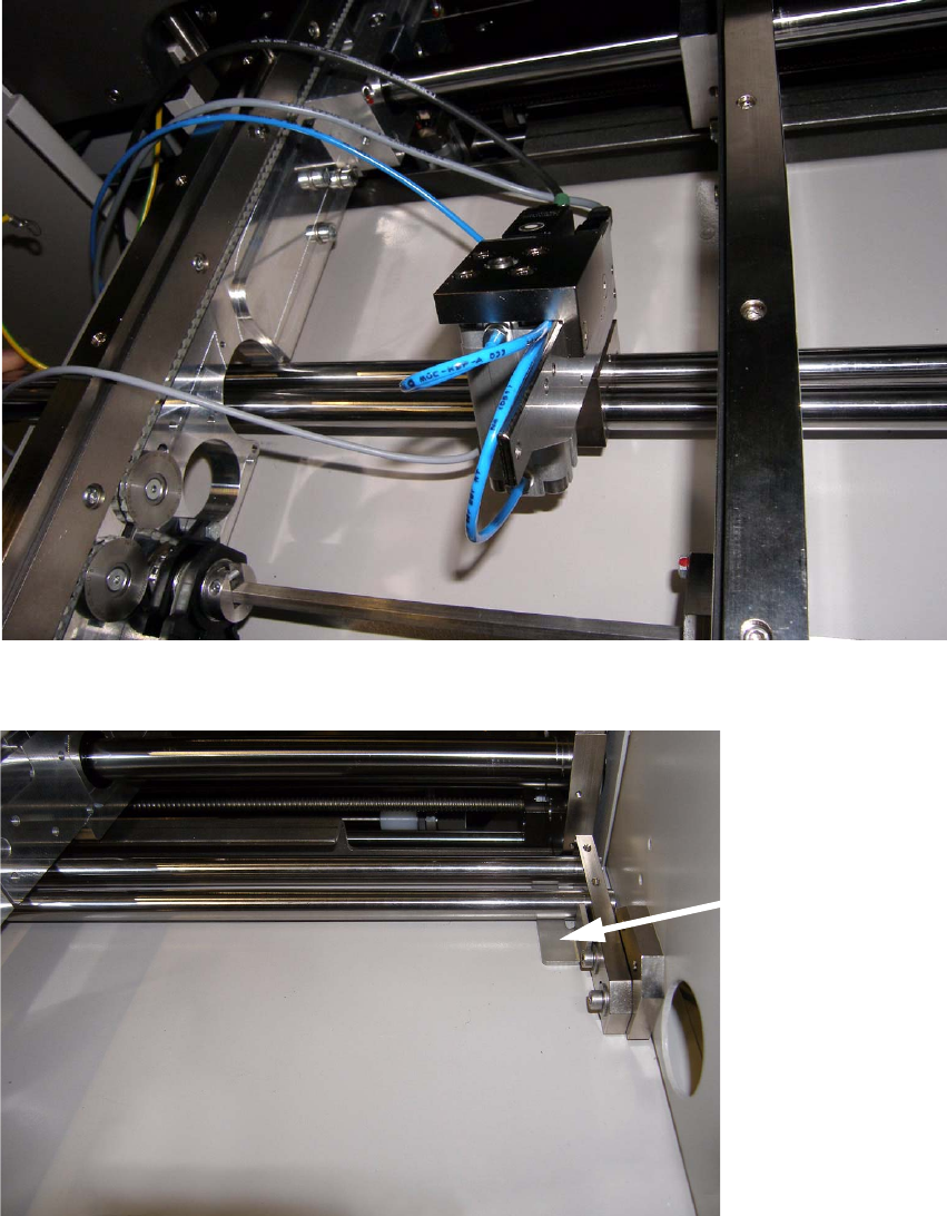
: Put the stopper unit between the conveyor side parts and pull both guiding shafts through the
stopper unit and fix it at the left side frame (hexagon sockets).
2
Fig. 2.11 - 4 Mounting of stopper unit
2
Fig. 2.11 - 5 Fixing of stopper (left side)
2
Adjustment gauge
for guiding shafts
LBO 50 mm SIPLACE D4 2 Assembly instructions SOKO Stopper LBO for minimum board size 50 mm SIPLACE D4
11/2007 Edition
35
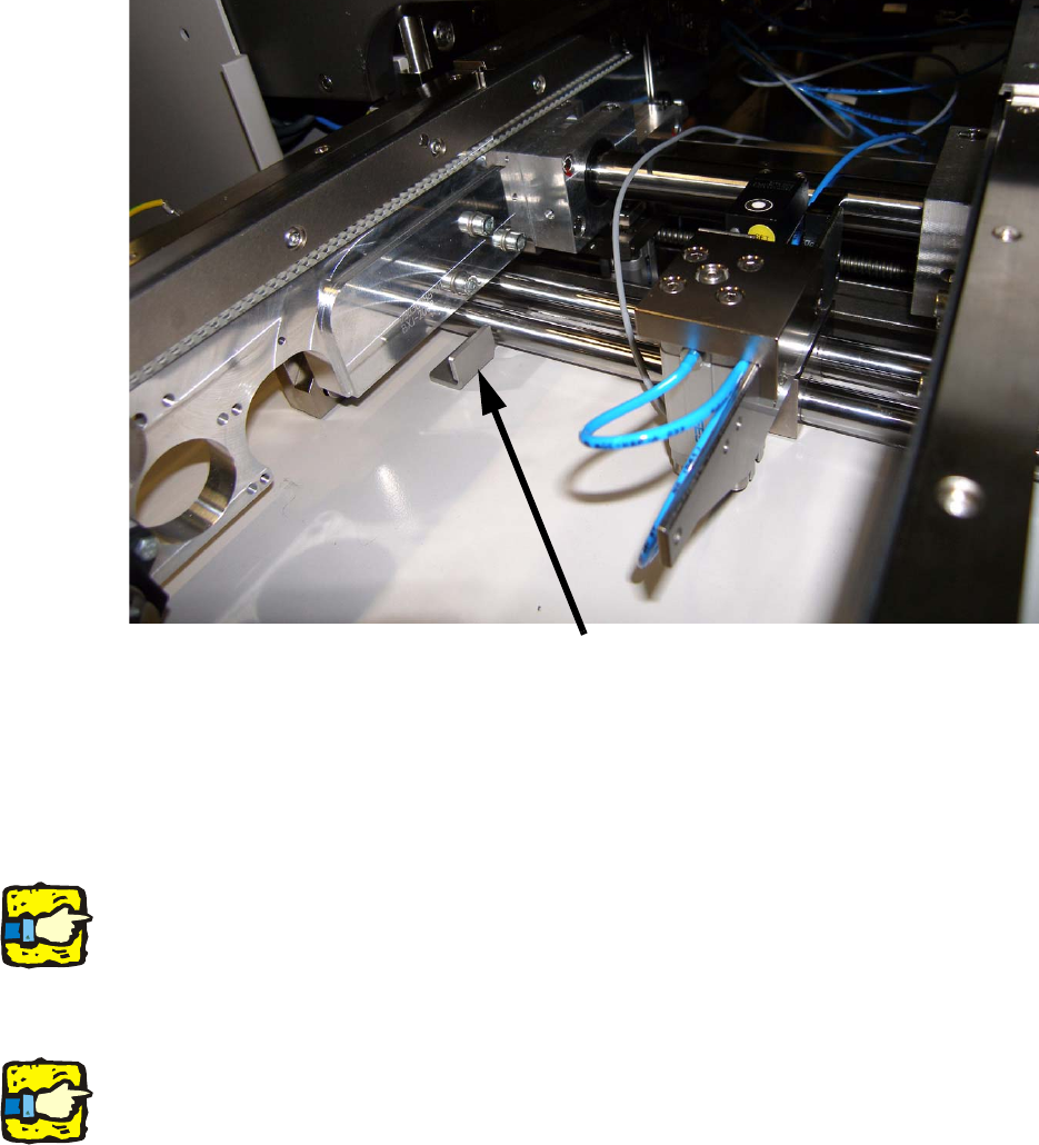
: Tighten the fixing for the guiding shafts easily.
: Mount the right cover of the output conveyor and tighten the fixing.
2
Fig. 2.11 - 6 Fixing of stopper (right side)
2
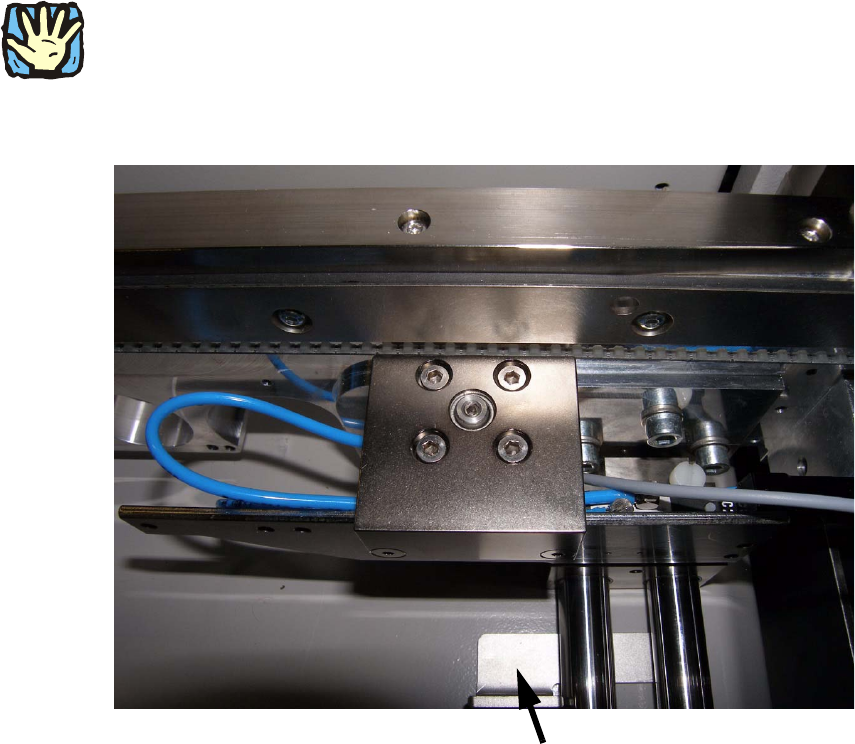
: Loosen the screws on the left and right fixing.
2
The position in x-direction is fixed. The guiding shafts have to be mounted on the same level on
both sides. 2
2
: Adjust the level of the guiding shafts with the delivered adjustment gauge.
2
Both guiding shafts have to be on the same level. The setting can be tested by adjusting the con-
veyor width from 50 to 460 mm. 2
2
2
2
2
Adjustment gauge for guiding shafts
2 Assembly instructions SOKO Stopper LBO for minimum board size 50 mm SIPLACE D4 LBO 50 mm SIPLACE D4
11/2007 Edition
36
2
ATTENTION:
In case of a crash of the conveyor side parts with the guiding shafts, press the STOP button and
check the position of guiding shafts. 2
2
2
Fig. 2.11 - 7 Adjusting level of guiding shafts
2
2
2
2
2
2
2
2
2
2
Adjustment gauge for guiding shafts