LBO für minimale LP-Breite 50mm an D4 - 第40页
2 Assembly instructions SOKO St opper LBO for minimum board size 50 mm SIPLACE D4 LBO 50 mm SIPLACE D4 11/2007 Edition 40 : S tore the plug and socket connection from th e adapter cable to the sensors and the stop per un…
LBO 50 mm SIPLACE D4 2 Assembly instructions SOKO Stopper LBO for minimum board size 50 mm SIPLACE D4
11/2007 Edition
39
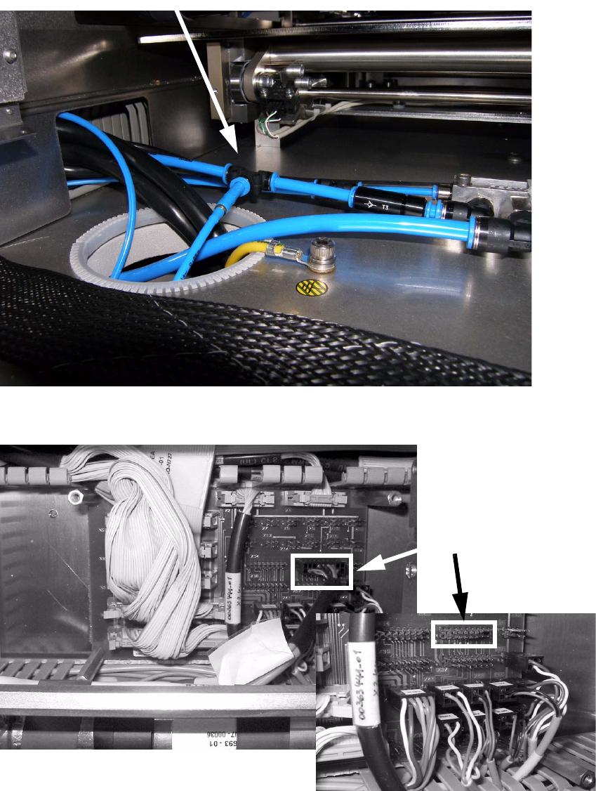
: Connect the pneumatic tube with the central air supply in the area between both placement
areas.
2
: Connect the adapter cable xxxxx to X35 at the conversion board.
2
Connection to the central air supply
X 35
2 Assembly instructions SOKO Stopper LBO for minimum board size 50 mm SIPLACE D4 LBO 50 mm SIPLACE D4
11/2007 Edition
40
: Store the plug and socket connection from the adapter cable to the sensors and the stopper
unit in the cable duct near the conversion board.
2
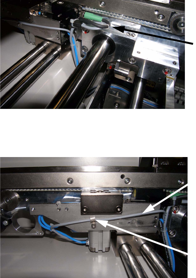
: Guide the wiring from the stopper unit and the supersonic sensor in a loop in horizontal direc-
tion (no contact to movable parts of the conveying system) and store ot together with the cable
from the sensor "stopper position" in the cable duct.
2
2
: Guide the cable from the sensor "stopper position" underneath the Festo drum and link it toge-
ther with the pneumatic tubes.
2
2
2
2
Cable layout to
supersonic sensor
Signal cable "Bero
stopper position"
Guidance of cable
LBO 50 mm SIPLACE D4 2 Assembly instructions SOKO Stopper LBO for minimum board size 50 mm SIPLACE D4
11/2007 Edition
41
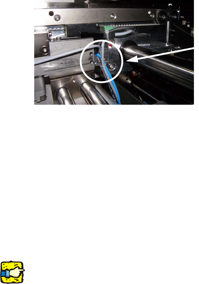
: Fix the cable from the sensor "stopper position" with a clamp at the side cover of the stopper
unit and guide it to the cable duct.
Guide the pneumatic tubes in the middle of the stopper unit and link it with the sensor cables
and guide it together in the cable duct.
2
2.1.3 Final operations
: Assemble the cover of the conversion board.
: Assemble the cover of the cable ducts in placement area 2.
: Assemble the lifting table in placement area 2.
: Mount the cover of the output conveyor..
2.1.4 Adjustment of the supersonic sensor (Baumer)
: Separate the supersonic sensor from the power supply.
: Keep the "SET" button pushed for 3 seconds. The LED at the sensor starts to blink.
: Place the PCB in the output conveyor and push the "SET" button again.
The clearance between sensor and PCB is teached.
2
PCBs with warpage have to be teached separately! 2
Bundling pneumatic
hoses and signal cables