D3操作手册 - 第12页
12 Placement Hea ds Collect & Place Heads Technical Data for the C & P Heads 12-nozzle Collect & Place he ad (standard- componen t cam era) 12-nozzl e Colle ct & Plac e head (high-re solution comp onent c…
11
Placement Heads
6-Nozzle Collect&Place Head for High-
Speed IC Placement
Description
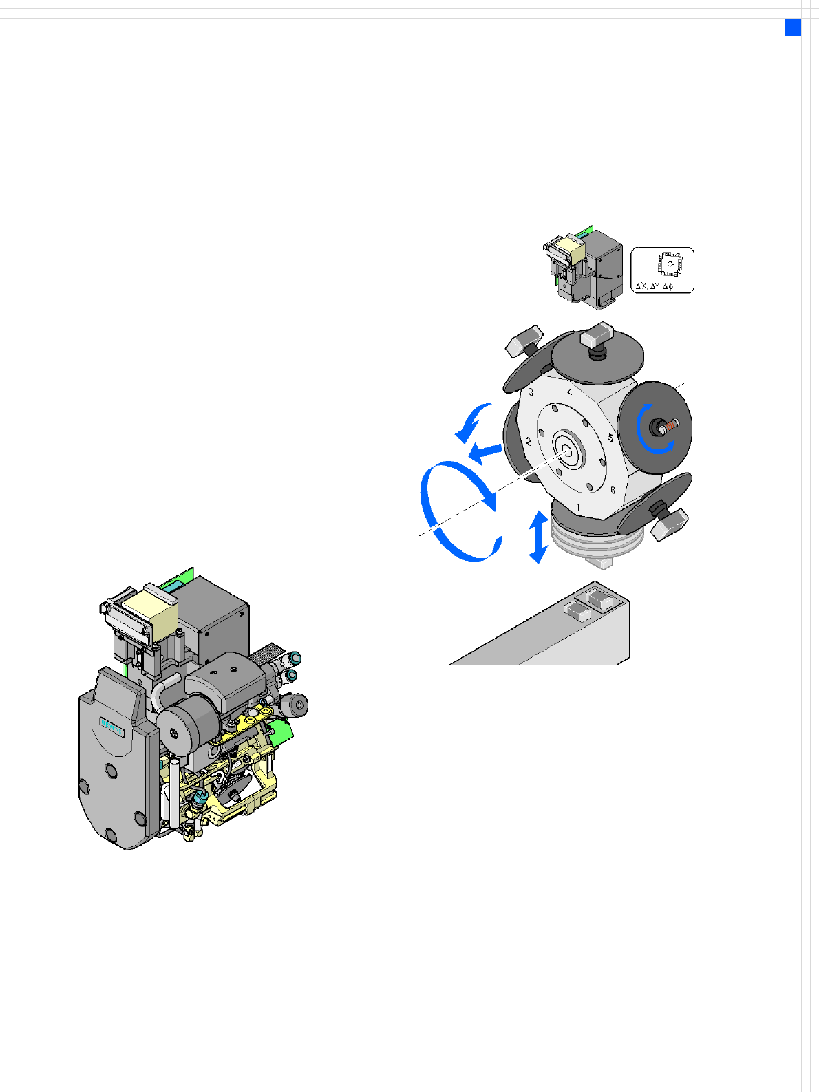
The 6-nozzle Collect & Place
head also works on the Col-
lect & Place principle. The
high-resolution digital com-
ponent camera allows the
6-nozzle Collect & Place head
to optically center and place
component sizes ranging
from 0201 to 27 x 27 mm².
Checking and self-learning
functions
The checking and self-learn-
ing functions described on
page 10 for the 12-nozzle
Collect & Place head also
apply to the 6-nozzle Collect
& Place head.
Component vision module
DP axis:
Rotate component
to placement angle
Z axis
Pick up or place component
DR axis:
Rotate star
Reject component,
pull off or
insert sleeve
12
Placement Heads
Collect&Place Heads
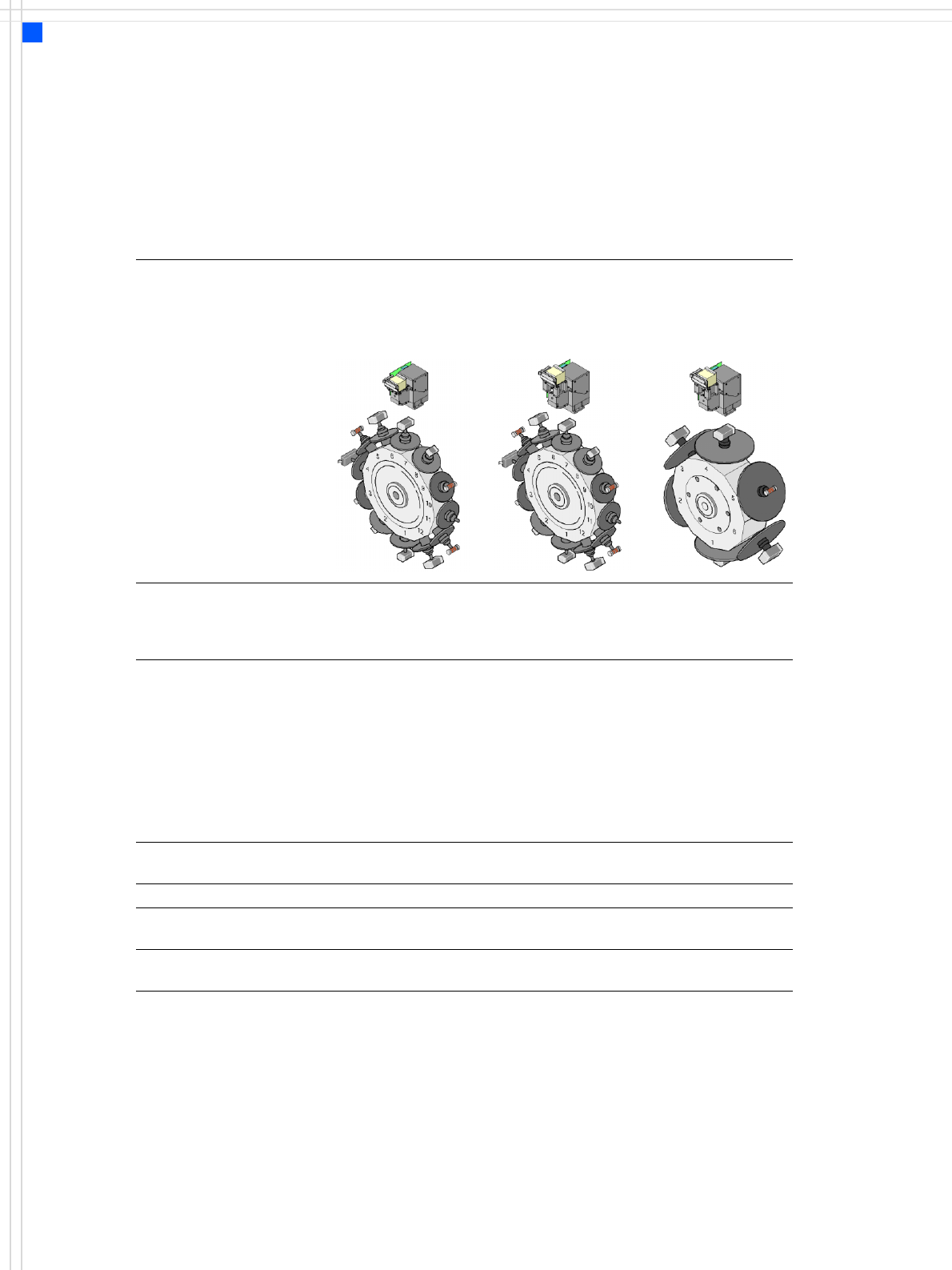
Technical Data for the C&P Heads
12-nozzle
Collect & Place head
(standard-
component camera)
12-nozzle
Collect & Place head
(high-resolution
component camera)
6-nozzle Col-
lect&Place head
Component range
a
a) Please note that the range of components that can be placed is also affected by the pad geometry,
customer-specific standards, component packaging tolerances and component tolerances.
0402 to PLCC44, BGA,
μBGA, flip-chip, TSOP,
QFP, SO to SO32, DRAM
01005
b
0201
c
to flip-
chip, bare die, PLCC44,
BGA, μBGA, TSOP, QFP,
SO to SO32, DRAM
b) 01005 optional, from April 2007
c) with 0201 package
0201 to 27 x 27 mm²
Component specification
max. height
min. lead pitch
min. ball pitch
min. ball diameter
min. dimensions
max. dimensions
max. weight
6 mm
0.5 mm
0.45 mm
0.25 mm
0.5 x 0.5 mm²
18.7 x 18.7 mm²
2 g
6 mm
0.3 mm
0.25 mm
0.14 mm
0.3 x 0.3 mm²
18.7 x 18.7 mm²
2 g
8.5 mm
0.3 mm
0.25 mm
d
0.35 mm
e
0.14 mm
d
0.2 mm
e
0.3 x 0.3 mm²
27 x 27 mm²
5 g
d) for components < 18 x 18 mm²
e) for components ≥ 18 x 18 mm²
Programmable placement
force
2.4 N - 5.0 N 2.4 N - 5.0 N 2.4 N - 5.0 N
Nozzle types 9 xx 9 xx 8 xx, 9 xx
X/Y accuracy ± 45 μm/3 σ
± 60 μm/4 σ
± 41 μm/3 σ
± 55 μm/4 σ
± 45 μm/3 σ
± 60 μm/4 σ
Angular accuracy ± 0.5°/3 σ
± 0.7°/4 σ
± 0.5°/3 σ
± 0.7°/4 σ
± 0.2°/3 σ
± 0.3°/4 σ
13
Placement Heads
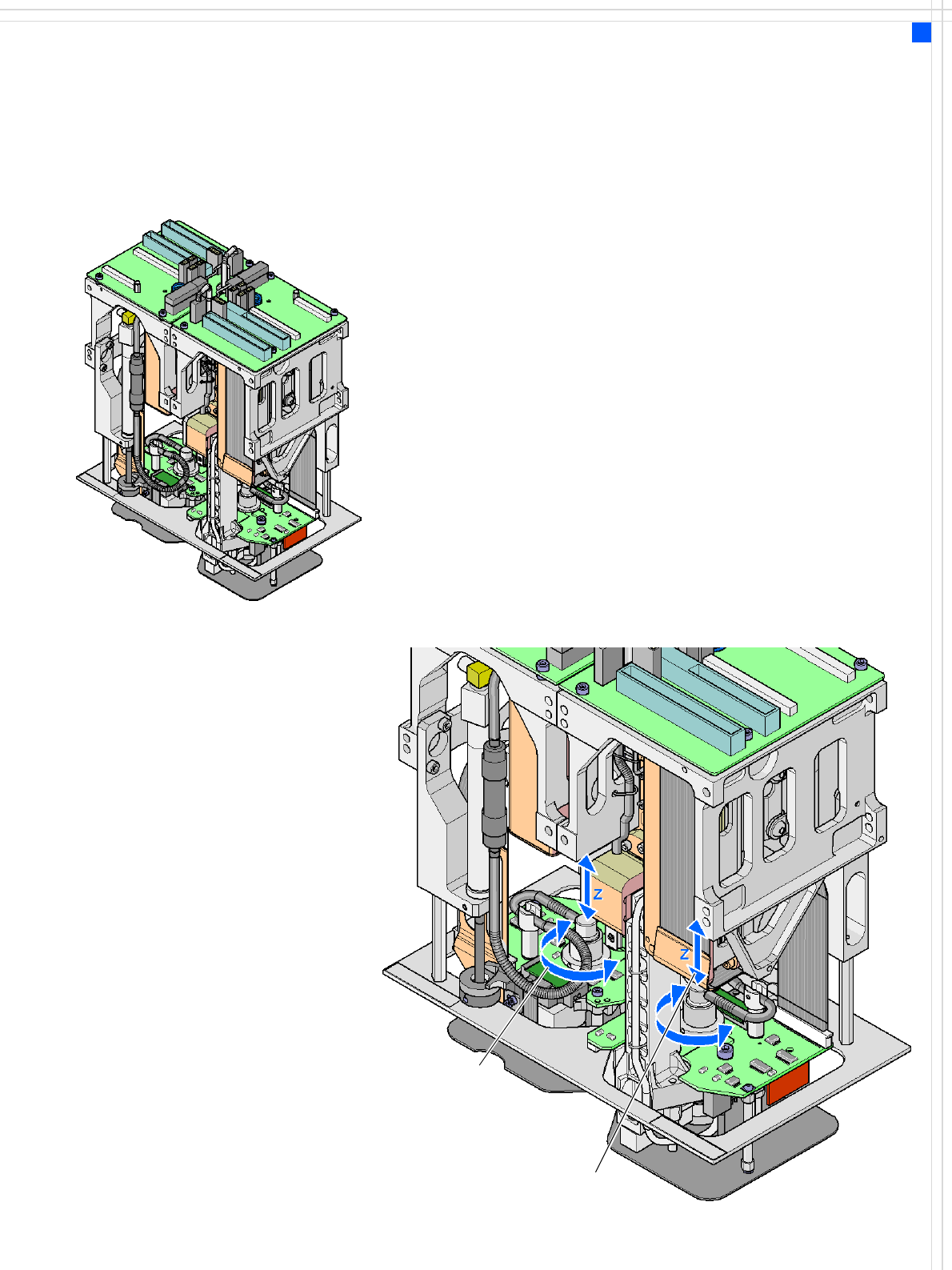
TwinHead for High-Precision IC Placement
Description
This sophisticated placement
head consists of two place-
ment heads of the same type
coupled together (twin
head). Both heads work
using the Pick & Place prin-
ciple. The TwinHead is suit-
able for processing
particularly difficult or large
components. Two compo-
nents are picked up by the
placement head, optically
centered on the way to the
placement position and ro-
tated into the necessary
placement angle. The com-
ponents are then placed
gently and accurately on the
board.
The placement head can also
use the nozzles for the Pick &
Place head (used on the F5
HM) in addition to the
nozzles recently developed
for the TwinHead.
Collect &Place head nozzles
can also be used.
Checking and self-learning
functions
The TwinHead's reliability
can be further increased with
various checking and self-
learning functions.
• For example, vacuum
checks at the nozzles indi-
cate whether the compo-
nent was picked up or
correctly.
• High-resolution, digital
component vision camer-
as such as the Fine-pitch
and Flip-chip vision camer-
as (optional) identify the
smallest deviations in the
component position. The
digital vision system cor-
rects such deviations, thus
guaranteeing a correct
placement position. The
digital component camer-
as are permanently fixed
to the machine frame.
• The component package
form is also checked and
the component is not
placed if the geometric
data thus determined dif-
fers from the programmed
data.
• A force sensor measures
and monitors the specified
component placement
forces.
Z axis
DP axis
How the TwinHead works