D3操作手册 - 第13页
13 Placement Heads TwinHead for High-Pre cision IC Placement Description This sophisti cated placem ent head consists of t wo place- ment heads o f the sa me type coupled toge ther (twi n head). Both hea ds work using th…
12
Placement Heads
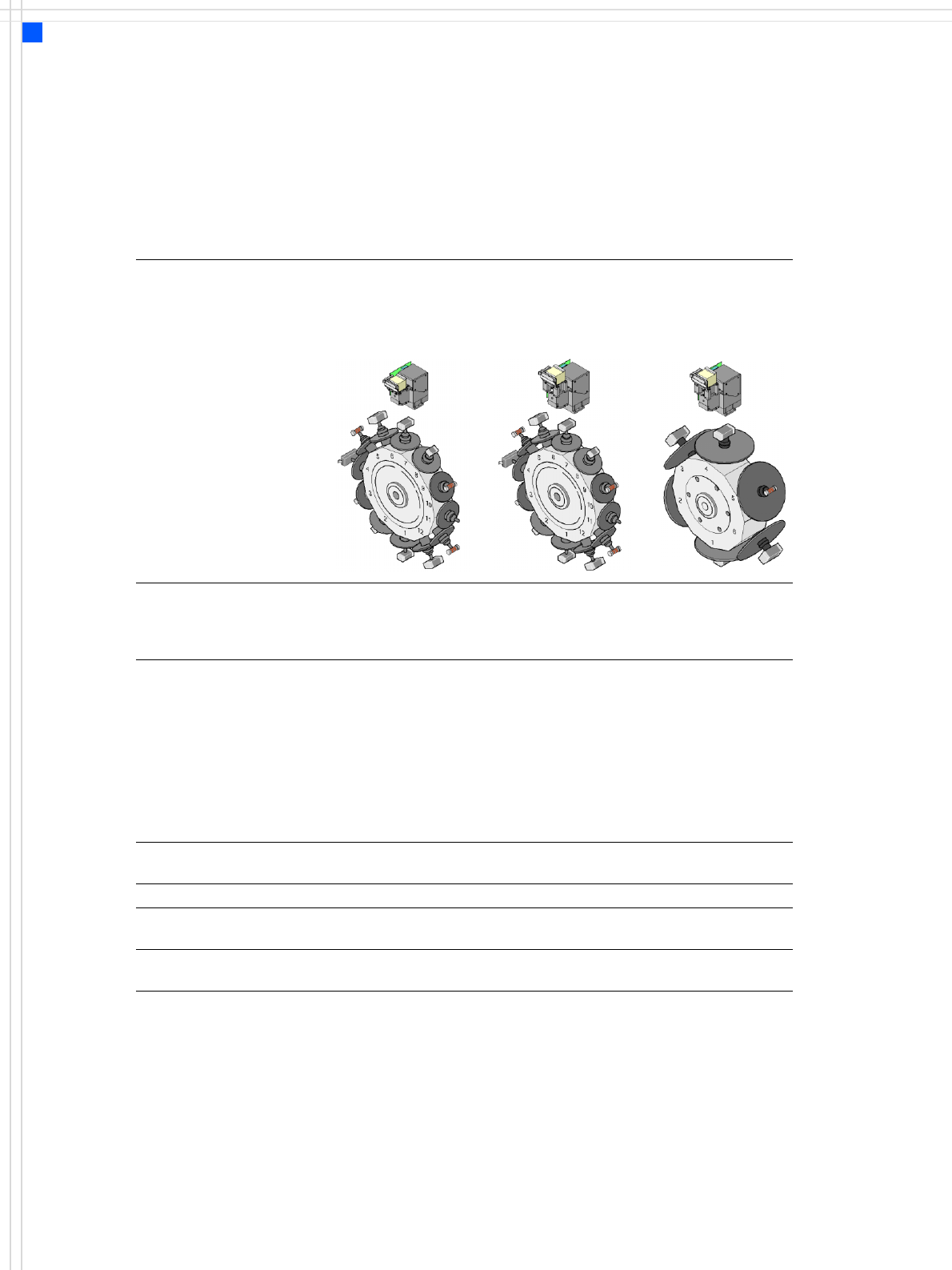
Collect&Place Heads
Technical Data for the C&P Heads
12-nozzle
Collect & Place head
(standard-
component camera)
12-nozzle
Collect & Place head
(high-resolution
component camera)
6-nozzle Col-
lect&Place head
Component range
a
a) Please note that the range of components that can be placed is also affected by the pad geometry,
customer-specific standards, component packaging tolerances and component tolerances.
0402 to PLCC44, BGA,
μBGA, flip-chip, TSOP,
QFP, SO to SO32, DRAM
01005
b
0201
c
to flip-
chip, bare die, PLCC44,
BGA, μBGA, TSOP, QFP,
SO to SO32, DRAM
b) 01005 optional, from April 2007
c) with 0201 package
0201 to 27 x 27 mm²
Component specification
max. height
min. lead pitch
min. ball pitch
min. ball diameter
min. dimensions
max. dimensions
max. weight
6 mm
0.5 mm
0.45 mm
0.25 mm
0.5 x 0.5 mm²
18.7 x 18.7 mm²
2 g
6 mm
0.3 mm
0.25 mm
0.14 mm
0.3 x 0.3 mm²
18.7 x 18.7 mm²
2 g
8.5 mm
0.3 mm
0.25 mm
d
0.35 mm
e
0.14 mm
d
0.2 mm
e
0.3 x 0.3 mm²
27 x 27 mm²
5 g
d) for components < 18 x 18 mm²
e) for components ≥ 18 x 18 mm²
Programmable placement
force
2.4 N - 5.0 N 2.4 N - 5.0 N 2.4 N - 5.0 N
Nozzle types 9 xx 9 xx 8 xx, 9 xx
X/Y accuracy ± 45 μm/3 σ
± 60 μm/4 σ
± 41 μm/3 σ
± 55 μm/4 σ
± 45 μm/3 σ
± 60 μm/4 σ
Angular accuracy ± 0.5°/3 σ
± 0.7°/4 σ
± 0.5°/3 σ
± 0.7°/4 σ
± 0.2°/3 σ
± 0.3°/4 σ
13
Placement Heads
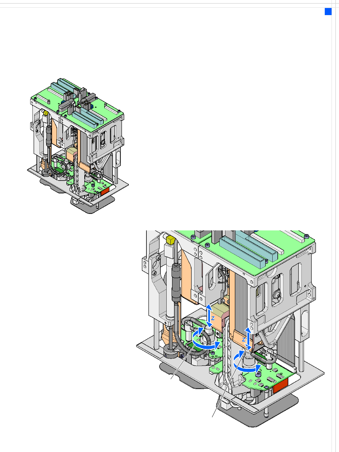
TwinHead for High-Precision IC Placement
Description
This sophisticated placement
head consists of two place-
ment heads of the same type
coupled together (twin
head). Both heads work
using the Pick & Place prin-
ciple. The TwinHead is suit-
able for processing
particularly difficult or large
components. Two compo-
nents are picked up by the
placement head, optically
centered on the way to the
placement position and ro-
tated into the necessary
placement angle. The com-
ponents are then placed
gently and accurately on the
board.
The placement head can also
use the nozzles for the Pick &
Place head (used on the F5
HM) in addition to the
nozzles recently developed
for the TwinHead.
Collect &Place head nozzles
can also be used.
Checking and self-learning
functions
The TwinHead's reliability
can be further increased with
various checking and self-
learning functions.
• For example, vacuum
checks at the nozzles indi-
cate whether the compo-
nent was picked up or
correctly.
• High-resolution, digital
component vision camer-
as such as the Fine-pitch
and Flip-chip vision camer-
as (optional) identify the
smallest deviations in the
component position. The
digital vision system cor-
rects such deviations, thus
guaranteeing a correct
placement position. The
digital component camer-
as are permanently fixed
to the machine frame.
• The component package
form is also checked and
the component is not
placed if the geometric
data thus determined dif-
fers from the programmed
data.
• A force sensor measures
and monitors the specified
component placement
forces.
Z axis
DP axis
How the TwinHead works
14
Placement Heads
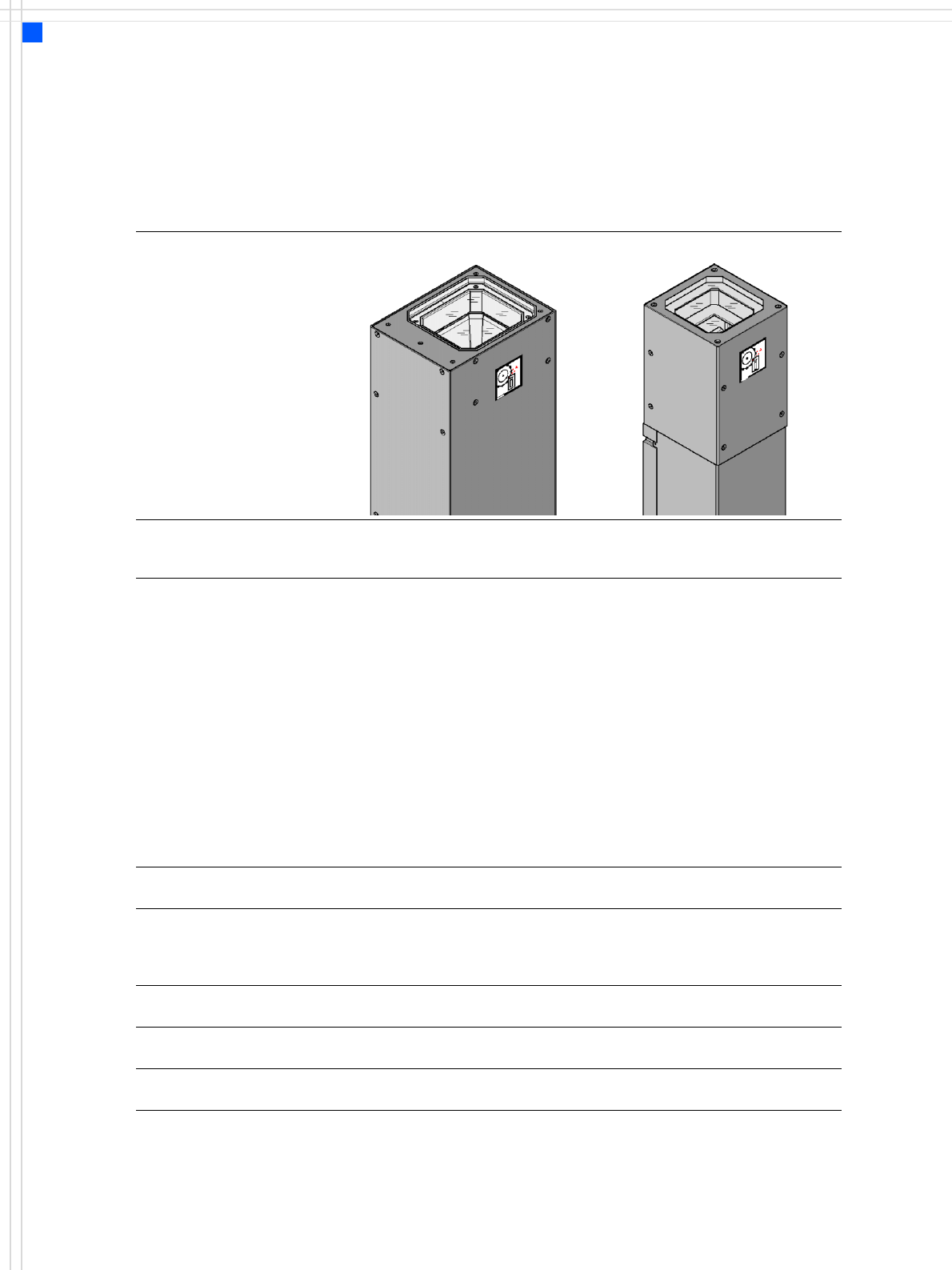
TwinHead for High-Precision IC Placement
Technical Data for the TwinHead
Optical centering with digital Fine-Pitch Camera Flip-Chip Camera (Option)
Component range
a
a) Please note that the range of components that can be placed is also affected by the pad geometry,
customer-specific standards, component packaging tolerances and component tolerances.
0402 to SO, PLCC, QFP, BGA, special
components, bare dies, flip-chips
0402 to SO, PLCC, QFP, sockets,
plugs, BGA, special components,
bare dies, flip-chips, shields
Component specification
max. height
min. lead pitch
min. ball pitch
min. ball diameter
min. dimensions
max. dimensions
max. weight
25 mm (larger heights on request)
0,3 mm
0,45 mm
0.25 mm
0.5 x 0.5 mm²
55 x 45 mm²
(single measurement)
For use with two nozzles
50 x 50 mm² or
69 x 10 mm²
For use with one nozzle:
85 x 85 mm² or
125 x 10 mm²
max. 200 x 125 mm² (with restrictions)
100 g
b
b) if standard nozzles are used
25 mm (larger heights on request)
0.25 mm
0,14 mm
0.08 mm
0.2 x 0.2 mm²
16 x 16 mm²
(single measurement)
100 g
b
Programmable placement
force 1.0 N - 15 N 1.0 N - 15 N
Nozzle types 5 xx (standard)
4 xx + adapter
8 xx + adapter
9 xx + adapter
5 xx (standard)
4 xx + adapter
8 xx + adapter
9 xx + adapter
Nozzle spacing on the two
Pick&Place heads
70.8 mm 70.8 mm
X/Y accuracy ± 26 μm/3σ
± 35 μm/4σ
± 22 μm/3σ
± 30 μm/4σ
Angular accuracy ± 0.05°/3σ
± 0.07°/4σ
± 0.05°/3σ
± 0.07°/4σ