D3操作手册 - 第31页
31 Component Feeding Matrix Tray Changer Technical Data Electrical ratings Nois e emissio ns Permitted environmen tal fact ors Supply voltage 3 x 400 VAC, 50 Hz (Europe) 3 x 208 VAC, 60 Hz (USA) Total power 1.5 kW Rated …

30
Component Feeding
Matrix Tray Changer
Technical Data
Tray supply 1 (XL) Tray supply 2
Dimensions
Length x width
Height
1305 x 600 mm²
1490 mm for 830 mm PCB transport height
1560 mm for 900 mm PCB transport height
1590 mm for 930 mm PCB transport height
1640 mm for 950 mm PCB transport height
Weight (basic equipment)
approx. 500 kg (with PCB magazines
and waffle-pack tray holders)
Weight (fully equipped)
approx. 534 kg (with components)
Weight (moving mass)
approx. 80 kg approx. 43.5 kg
PCB magazine size (L x W x H)
391.2 x 305.6 x 93.3 mm³ 352.7 x 154.8 x 133.8 mm³
PCB magazine weight
(fully equipped)
(without waffle-pack tray holders)
approx. 11 kg
approx. 1.7 kg
approx. 7.5 kg
approx. 1.35 kg
Waffle-pack tray holder weight
850 g 150 g
Waffle-pack tray holders dimensions
(L x W x H)
386.5 x 295.8 x 11.1 mm³ 371 x 146 x 10.1 mm³
Distance from PCB magazine to maga-
zine
96 mm 135 mm
Distance from level to level
12 mm 11.8 mm
Vertical travel
444 mm
(1st to 30th waffle-pack
tray holder)
511.2 mm
(1st to 40th waffle-pack tray
holder)
Horizontal travel between
outgoing and pick-up position
approx. 647 mm approx. 638 mm
Storage capacity
30 XL waffle-pack tray hold-
ers with 60 JEDEC or
30 special magazines of
maximum size
40 waffle-pack tray holders
with
40 JEDEC waffle-pack trays
Changeover time (over 5 levels)
approx. 2 sec approx. 1.5 sec
Max. height of component and waffle
tray, including tolerances
all levels filled
one level free
two levels free
8.5 mm
19.5 mm
31.5 mm
8.5 mm
19.5 mm
–

31
Component Feeding
Matrix Tray Changer
Technical Data
Electrical ratings
Noise emissions
Permitted environmental factors
Supply voltage 3 x 400 VAC, 50 Hz (Europe)
3 x 208 VAC, 60 Hz (USA)
Total power 1.5 kW
Rated current 2.7 A at 3 x 400 VAC
4.2 A at 3 x 208 VAC
Fuses 3 x 16 A
Rated power consumption of the largest consumer 2 A
Maximum noise emissions 74 dB (A)
Room temperature between 15 °C and 35 °C
Atmospheric humidity 30 - 75 %
(No higher than 45% on average to prevent any possibil-
ity of condensation on the machine)
32
Vision Sensor Technology
PCB Position Recognition
Technical data
PCB fiducials
Local fiducials
Library memory f. recog-
nition of bad panels
up to 3 (subpanels and multiple panels)
up to 6 for the Long board option
(Optional PCB fiducials are output by
the optimization.)
up to 2 per PCB (may be of different
type)
up to 255 fiducial types per subpanel
Image analysis Edge detection method (Singular fea-
ture) based on grayscale values
Lighting method Front lighting
Fiducial recognition time 0.1 s
Field of vision 5.78 x 5.78 mm²
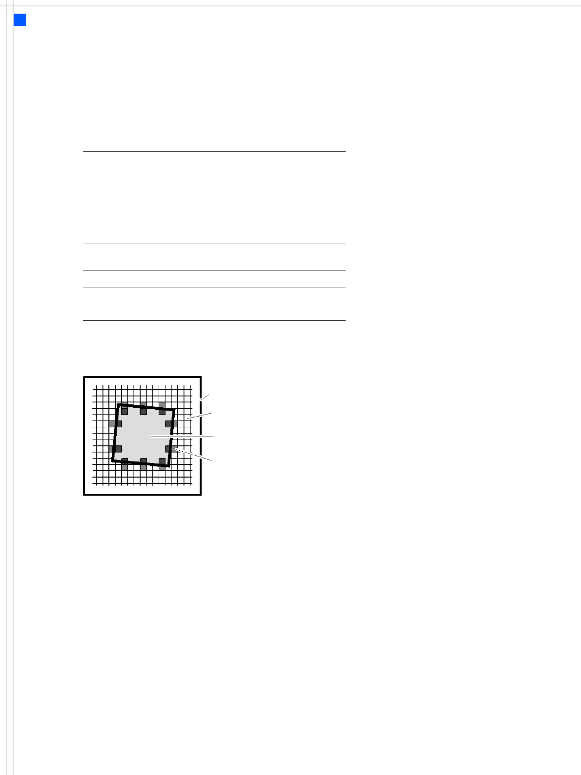
Camera’s field of view
Pixel
Ink spot, e.g. square
Evaluation window
Edge detection method
The size of the fiducial is pro-
grammed at the station com-
puter. From this time on form
and size of the fiducial is de-
fined and known. With these
data the PCB vision module is
able to search and recognize
the fiducial at the predefined
position on the PCB or ceram-
ic substrate without further
assistance. For this reason it
places several small evalua-
tion windows at the assumed
border of the fiducial. Within
these evaluation windows
the vision system looks for
contrast transitions between
bright and dark. After finding
such contrasts the actual
position of the fiducial can be
assigned by comparison with
the predefined – and thus
known – shape and size.
The analysis operations can
be used to determine any off-
set with respect to the DE-
SIRED position in the X and Y
directions and the angular
position.
Alternatively, a fiducial may
be taught as a pattern.
Additional functions of the
PCB vision module are recog-
nition of the position of the
feeder modules and ceramic
substrate (optional) and
recording of the machine
data including mapping.
The bad board detector
(GOOD/SCRAP scan) is also
moved over the ink spot
using the PCB vision module.
Description
SIPLACE has a number of
vision modules and a central
vision system to evaluate the
recorded image data ensur-
ing high placement accuracy.
At the machine's X-gantry
the PCB vision module is
mounted. It is used to find
the PCB's positioning-offsets
within the conveyor system.
This vision module is also
required to measure the
machine origin and/or the
feeder module positions on
one side of the table. Each
vision module consists of a
single CCD camera with inte-
grated lighting and optics.
The offsets in the position of
the PCBs are determined with
the help of at least two but
generally three reference
fiducials on the PCB. When
the PCB arrives at the place-
ment area the positioning
system with its PCB vision
module moves to the pro-
grammed fiducial.
The edge detection method
allows to choose predefined
fiducials from a menu (e.g.
cross, circle, square).