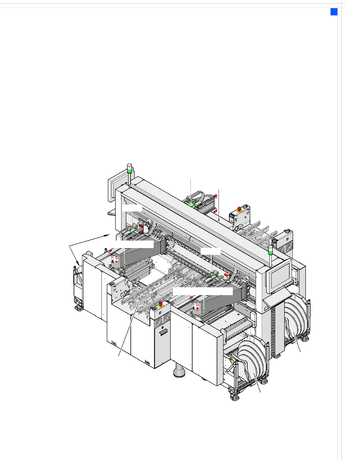
D3操作手册 - 第34页
34 Vision Sensor Technology Bad Board Recognition Position Recognition for Feeder Modules Ink Spot Crit eria Method s • Synt hetic fid ucial recogniti on method • Mean gr ayscal e val ue • Histogram m ethod • Templat e m…

33
Vision Sensor Technology
PCB Position Recognition
Description
Different fiducial shapes
prove to be optimal depend-
ing on the condition of the
surface.
Particularly advisable for bare
copper surfaces with little
oxidation is the single cross.
Maximum accuracy is
achieved due to the high in-
formation content. Rectan-
gle, square and circle are less
“informative” but save space
and can even be used when
oxidation is at an advanced
stage.
Advisable for tinned struc-
tures are circle or square be-
cause in this case the ratio of
the fiducial dimensions to
the presolder thickness is
particularly favorable.
Fiducial criteria
Locate 2 fiducials
Locate 3 fiducials
X-/Y-position, rotation angle, mean PCB distortion
in addition: shear, distortion in X- and Y-direction separately
Fiducial shapes Synthetic fiducials: circle, cross, square, rectangle, rhombus, circu-
lar, square, and rectangular contours, double cross, any pattern
Fiducial surface:
copper
tin
without oxidation and solder resist
Warp ≤ 1/10 of structure width, both with good contrast to envi-
ronment
Dimensions of synthetic fiducials
min. X/Y size for circle and rectangle: 0.25 mm
min. X/Y size for annulus and rectangle: 0.3 mm
min. X/Y size for cross: 0.3 mm
min. X/Y size for double-cross: 0.5 mm
min. X/Y size for lozenge: 0.35 mm
min. frame width for annulus and rectangle: 0.1 mm
min. bar width / bar distance for cross, double-cross: 0.1 mm
max. X/Y size for fiducial shapes: 3 mm
max. bar width for cross / double-cross: 1.5 mm
min. tolerances, general: 2% of nominal dimension
max. tolerances, general: 20% of nominal dimension
Dimensions of patterns
min. size
max. size
0.5 mm
3 mm
Fiducial environment Clearance around reference fiducial not necessary if there is no
similar fiducial structure in the search area

34
Vision Sensor Technology
Bad Board Recognition
Position Recognition for Feeder Modules
Ink Spot Criteria
Methods • Synthetic fiducial recognition
method
• Mean grayscale value
• Histogram method
• Template matching
Shapes and sizes of fiducials/
structures for
synthetic fiducials
other methods
For dimensions of synthetic fidu-
cials, see page 33
min. 0.3 mm
max. 5 mm
Masking material good coverage
Recognition time depends on the method:
20 ms - 0.2s
Description
In the cluster technology
each subpanel is assigned an
ink spot. If this is present dur-
ing the measurement via the
PCB vision module, the corre-
sponding subpanel is popu-
lated.
It is also possible to accom-
plish the population of the
subpanel when the ink spot is
missing. With this function it
is possible to eliminate costs
due to unnecessary popula-
tion of faulty subpanels.
Global Ink Spot
Each GOOD/SCRAP scan takes
some time, and the time re-
quired is even greater if there
are a large number of sub-
panels on a PCB. Using the
global ink spot can result in a
significant reduction of these
secondary times.
The PCB vision module
searches at positions taught
before for the defined fidu-
cial. In case of recognition
there is no following evalua-
tion of subpanels. The sys-
tem allows the operator to
choose also the reverse inter-
pretation.
Recognition of the position
of the feeder modules
The pick-up position of the
components can be deter-
mined precisely with the aid
of the position recognition
for the feeder. The offset in
position relative to the stored
ideal position is determined
on the basis of fiducials on
the feeder modules using the
PCB vision module. This pro-
vides very high pick-up reli-
ability even for the very first
component, which is particu-
larly important for small com-
ponents.
35
Sample Configuration
Services
As a service, SIEMENS A&D
EA can fully integrate the
SIPLACE D3 placement
machine into your produc-
tion line. With our extensive
expertise and by using the
right tools and equipment,
we can ensure that the instal-
lation process runs smoothly
and efficiently. However, this
will require you to clarify the
infrastructure aspects in ad-
vance and make any neces-
sary changes at your
production facility.
Safety instructions
Read the operating instruc-
tions before starting to set up
and commission the place-
ment machine. The applica-
ble accident prevention
regulations concerning the
transportation of heavy
goods must be followed.
Nozzle changer C&P12
Component
changeover table
with 15 locations
Nozzle Changer (TwinHead)
5-part conveyor belt
with automatic width adjustment
from 50 mm to 508 mm (2“ to 20“)
Nozzle Changer (TwinHead)
Component
changeover table
with 15 locations
Nozzle changer C&P12
Component changeover table
with 15 locations
C&P12
C&P12
TH