D3操作手册 - 第39页
39 Technical Data SMEMA Interface Signal Curve 1 . Af ter sw i tc hi ng on t h e stat i on Transp ort di rect ion Belt n Belt n +1 PCB sensor PCB sens or Station n transports PCB to the transfer position Belt n runnin g …

38
Technical Data
SMEMA Interface
Connector Assignment
Signal interface (14-pole connecting socket, interface standard 1.2)
Upstream station X1 Downstream station X2
Pin 1NOT READY + Pin 1NOT READY +
Pin 2NOT READY – Pin 2NOT READY –
Pin 3 BOARD AVAILABLE + Pin 3 BOARD AVAILABLE +
Pin 4 BOARD AVAILABLE – Pin 4 BOARD AVAILABLE –
Pin 5 Not used Pin 5 Not used
Pin 6 Not used Pin 6 Not used
Pin 7 Not used Pin 7 Not used
Pin 8 Reserved Pin 8 Reserved
Pin 9 Reserved Pin 9 Reserved
Pin 10 Reserved Pin 10 Reserved
Pin 11 Reserved Pin 11 Reserved
Pin 12 Reserved Pin 12 Reserved
Pin 13 Reserved Pin 13 Reserved
Pin 14 Reserved Pin 14 Reserved
39
Technical Data
SMEMA Interface
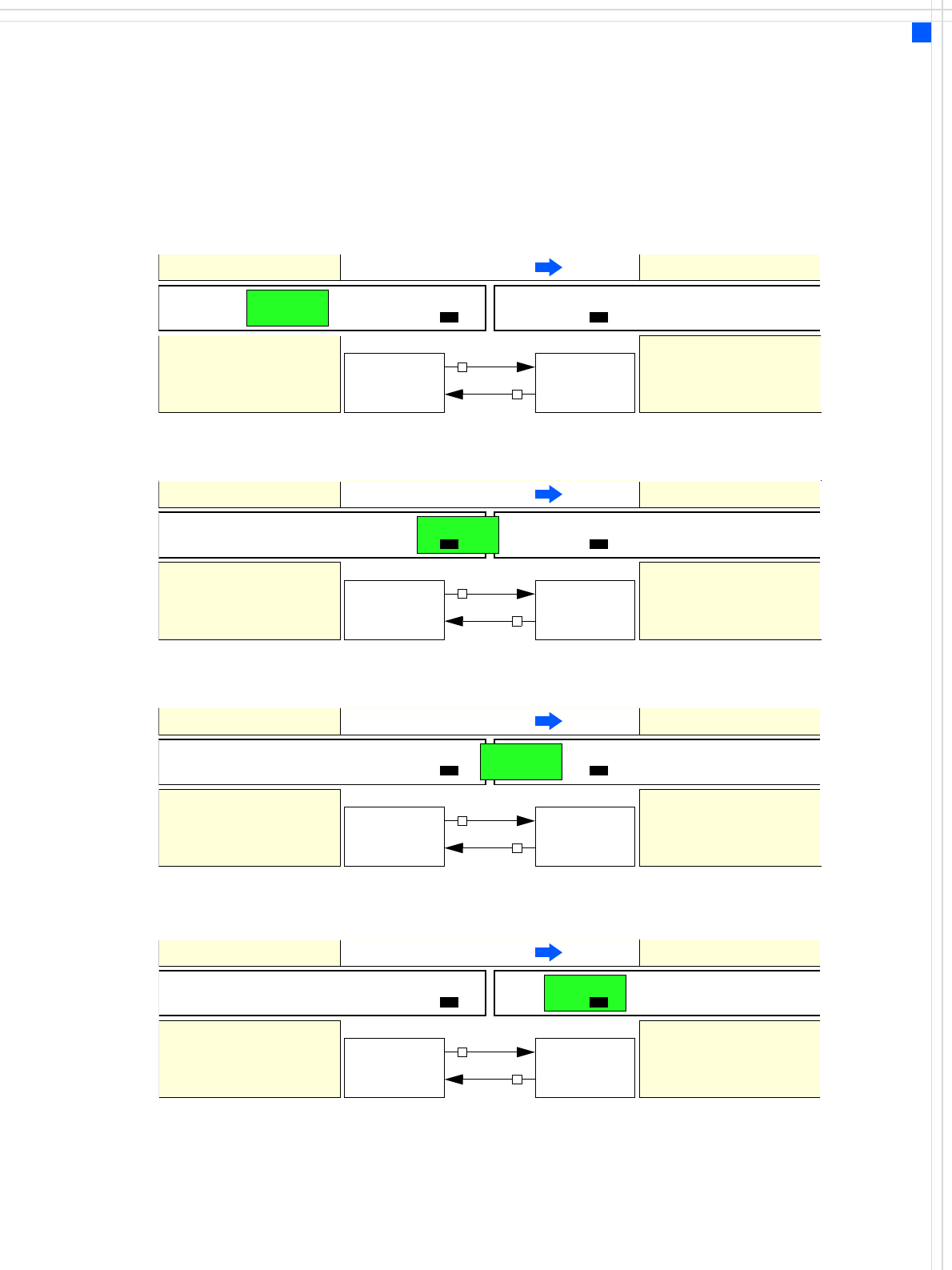
Signal Curve
1
.
Af
ter sw
i
tc
hi
ng on t
h
e stat
i
on
Transport direction
Belt n Belt n+1
PCB sensor PCB sensor
Station n transports
PCB to the transfer position
Belt n running Belt n+1 stopped
BOARD AVAILABLE
Permission
Station n+1
is not ready
1
0
2. The PCB transfer has started
Transport direction
Belt n Belt n+1
PCB sensor
Station n transfers
PCB to Station n+1
Belt n running Belt n+1 running
Station n+1 expects
PCB from station n
3. PCB is transferred
Transport direction
Belt n Belt n+1
PCB sensor PCB sensor
Station n has
just transferred the PCB
Belt n stopped Belt n+1 running
Station n+1 expects PCB
from station n, but PCB
has not yet arrived.
PCB sensor
4. PCB transfer is complete
Transport direction
Belt n Belt n+1
PCB sensor PCB sensor
Station n
Belt n stopped Belt n+1 running
Station n+1
PCB arrived
Request
NOT READY
BOARD AVAILABLE
Permission
1
1
Request
NOT READY
BOARD AVAILABLE
Permission
0
1
Request
NOT READY
BOARD AVAILABLE
Permission
0
0
Request
NOT READY
To start a new PCB transfer, both signals must be "0" for at least 50 ms.

40
Technical Data
Electrical Ratings and
Compressed Air Supply
Electrical ratings
Supply voltage 3 x 208 VAC ± 5 %, 50/60 Hz (U.S.A. version)
3 x 230 VAC ± 5 %;50/60 Hz
3 x 380 VAC ± 5 %;50/60 Hz
3 x 400 VAC ± 5 %, 50/60 Hz (European version)
3 x 415 VAC ± 5 %;50/60 Hz
Fuses 3 x 32 A (3 x 208 VAC / 3 x 230 VAC)
3 x 16 A (3 x 380 VAC / 3 x 400 VAC / 3 x 415 VAC)
Nominal apparent power 4.1 kVA
Rated current consumption 9.7 A / 3 x 400 VAC
Power failure max. 20 msec
Compressed air supply
Compressed air ratings
p
min
p
max
0.5 MPa = 5.0 bar
1.0 MPa = 10 bar
Compressed air connection 3/4" thread with 1/2" hose connection
Compressed air consumption with 4 tape
cutters
2 x C&P12/TH 550 st. l/min
300 st. l/min with vacuum pump
Operating pressure 0.48 MPa ± 0.025 MPa (4.8 bar ± 0.25 bar)
Compressed air specification
Particle size 0.1 μm
Particle density 0.1 mg/m³
Maximum oil content (class 1) Particle density 0.01 mg/m³
Pressure dewpoint (class 4) Dewpoint + 3°C