D3操作手册 - 第7页
7 Machine Description Technical Data Types of plac ement head 12-nozzle Collec t & Place head (C&P 12) 6-nozzle Collec t & Place head (C&P 6) SIPLACE TwinHead (TH) Number of gantries 3 (see Fig. pag e 9) …
6
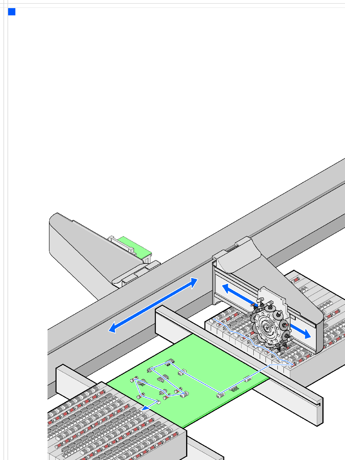
Placement principle
Collect & Place
Machine Description
Extensions
Extensions
The options available to ex-
tend the functionality of the
placement machine include
the following:
• Additional component
changeover tables in-
crease machine utilization
since set-up times can be
reduced by carrying out
preliminary set-up off the
machine.
• Large and sensitive fine-
pitch components can be
supplied in trays by a
matrix tray changer.
• The dual conveyor also in-
creases machine utiliza-
tion by eliminating non-
productive PCB transport
times.
• Automatic nozzle chang-
ers speed up and optimize
the nozzle configuration
process.
• PCB barcode scanners
allow the production set-
up to be changed over
when triggered by a new
product.
• Component barcode scan-
ners optimize the set-up
and refill checks.
• The productivity lift imple-
ments the concept of par-
allel placement, and thus
improves the ratio be-
tween productive and
non-productive times.

7
Machine Description
Technical Data
Types of placement head 12-nozzle Collect & Place head (C&P12)
6-nozzle Collect & Place head (C&P6)
SIPLACE TwinHead (TH)
Number of gantries 3 (see Fig. page 9)
Placement head configu-
ration and placement
rate
a
(Benchmark test)
a) According to the Definition in the SIPLACE Scope of Service and Delivery
Placement area 1 Placement area 2 Placement rate
C&P12 / C&P12 TH 30,100 comp./h
C&P12 / C&P6 TH 24,000 comp./h
C&P6 / C&P12 TH 24,000 comp./h
C&P6 / C&P6 TH 22,000 comp./h
Placement positions 6.000 / gantry for the Collect & Place head
Range of components 0.4 x 0.2 mm² (01005)
b
, 0.6 x 0.3 mm² (0201)
c
to 85 x 85 mm² / 125 x 10 mm²
max. 200 x 125 mm² (with restrictions)
b) 01005 optional, from April 2007
c) with 0201 package
Component height C&P12: 6 mm (larger heights on request)
C&P6: 8.5 mm (larger heights on request)
TH: 25 mm
Placement accuracy /
angular accuracy
C&P12: ± 45 μm, ± 0.5° / (3σ), ± 60 μm, ± 0.7° / (4σ)
(standard camera)
C&P12: ± 41 μm, ± 0.5° / (3σ), ± 55 μm, ± 0.7° / (4σ)
(high-resolution camera)
C&P6: ± 45 μm, ± 0.2° / (3σ), ± 60 μm, ± 0.3° / (4σ)
TH: ± 26 μm, ± 0.05° / (3σ), ± 35 μm, ± 0.07° / (4σ)
(Fine-Pitch Camera)
± 22 μm, ± 0.05° / (3σ), ± 30 μm, ± 0.07° / (4σ)
(Flip-Chip Camera)
Component Feeding 4 component changeover tables with tape roll holders and
integral waste containers
15 slots, 30 mm wide per changeover table or matrix tray
changer, rather than a component changeover table
(location 2)
Feeder module types Tapes, bulk cases, stick magazines, application-specific OEM
feeder modules, surftape feeder modules (8, 12, 16 mm),
waffle-pack trays
Feeding capacity 60 tape feeder modules 3 x 8 mm S (180 tracks)
60 tape feeder modules 2 x 8 mm S (120 tracks)
60 tape feeder modules 12/16 mm S (60 tracks)
40 tape feeder modules 24/32 mm S (40 tracks)
28 tape feeder modules 44 mm S (28 tracks)
24 tape feeder modules 56 mm S (24 tracks)
20 tape feeder modules 72 mm S (20 tracks)
16 tape feeder modules 88 mm S (16 tracks)

8
Machine Description
Technical Data
PCB format
(LxW)
PLEASE NOTE:
With PCB widths > 450 mm make
sure that the peripheral modules
are also able to process these
widths.
Single conveyor
50 x 50 mm² to 450 x 460 mm²
50 x 80 mm² to 610 x 460 mm² (Long board option)
(Width up to 508 mm available on request)
Flexible dual Conveyor
50 x 50 mm² to 450 x 216 mm²
50 x 80 mm² to 610 x 216 mm² (Long board option)
(Width up to 250 mm available on request)
Flexible dual conveyor in Single conveyor mode
50 x 50 mm² to 450 x 380 mm²
50 x 80 mm² to 610 x 380 mm² (Long board option)
(Width up to 450 mm available on request)
PCB thickness 0.3 - 4.5 mm (thicker PCBs on request)
Electrical ratings and
compressed air supply
see page 40
Dimensions of the placement
systems
see figure page 43