SIPLACE D系列Servicemanual.pdf - 第101页
Service Work White Balance Process for SIPLACE Di gital Vision Camera Placement Heads Servicemanual (internal version) SIPLACE D Series 101 4.2.3.4 The Illumination Calibration Process X The PCB camera is positioned to c…
Service Work
Placement Heads White Balance Process for SIPLACE Digital Vision Camera
100 Servicemanual (internal version) SIPLACE D Series
4.2.3.3 Preparing for Calibration
To ensure that customer setups do not need to be changed, a black calibration tool carrier is moved into
PCB conveyor 1, is optically centered and clamped into place, the presence of the white balance
calibration tools is checked and illumination calibration (white balance process) is started.
NOTE:
The XML files for the white balance process are created before beginning measurement. To
view the data for the current calibration in the XML file, perform the balance process (with 603/
604.01) again; without saving the data when you exit SITEST. The files will then be in the folder
C:\SR-Daten\FCCS
.
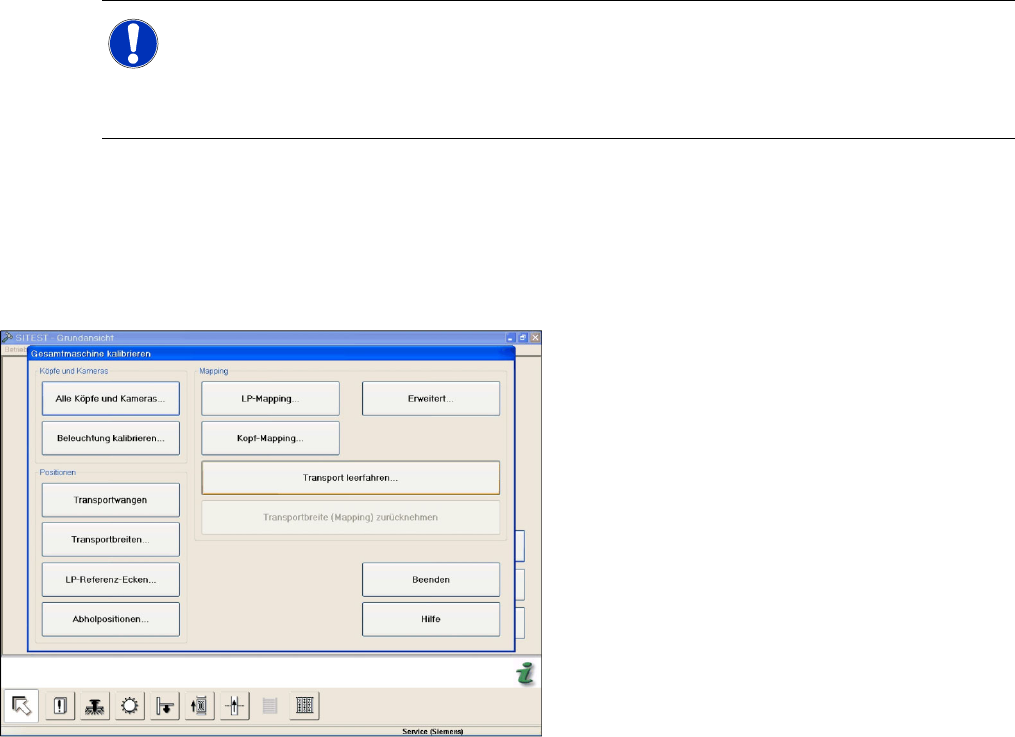
X Go to
Calibrate illumination
in the
Calibrate
Entire Machine
menu.
X In the calibration menu for the entire machine,
you can specify the camera for which the
process is to be conducted (all/placement
area1/placement area2/head).
X The width adjustment will then automatically
set the width of conveyor lane 1 to the width of
the tray.
X The nozzles required for the illumination
calibration will be shown, as will the current
head setup. You may need to terminate the
menu, in order to configure the nozzles at the
head or to pick them up from the nozzle
changer.
X If you have a second placement head at the
gantry, the setup for this will be shown in a
separate window.
X The SITEST software will now request that
you place the calibration tool carrier into the
input conveyor. (Do not push in as far as the
input conveyor sensor!) Confirm each step
with the OK button. In this step, the tray is
moved into the processing area and is
clamped into place.
Service Work
White Balance Process for SIPLACE Digital Vision Camera Placement Heads
Servicemanual (internal version) SIPLACE D Series
101
4.2.3.4 The Illumination Calibration Process
X The PCB camera is positioned to check the presence of the calibration tools. Fiducial recognition
determines whether all the calibration tools are present.
X The PCB camera centers the 3 fiducials for
position recognition of the calibration tool
carrier.
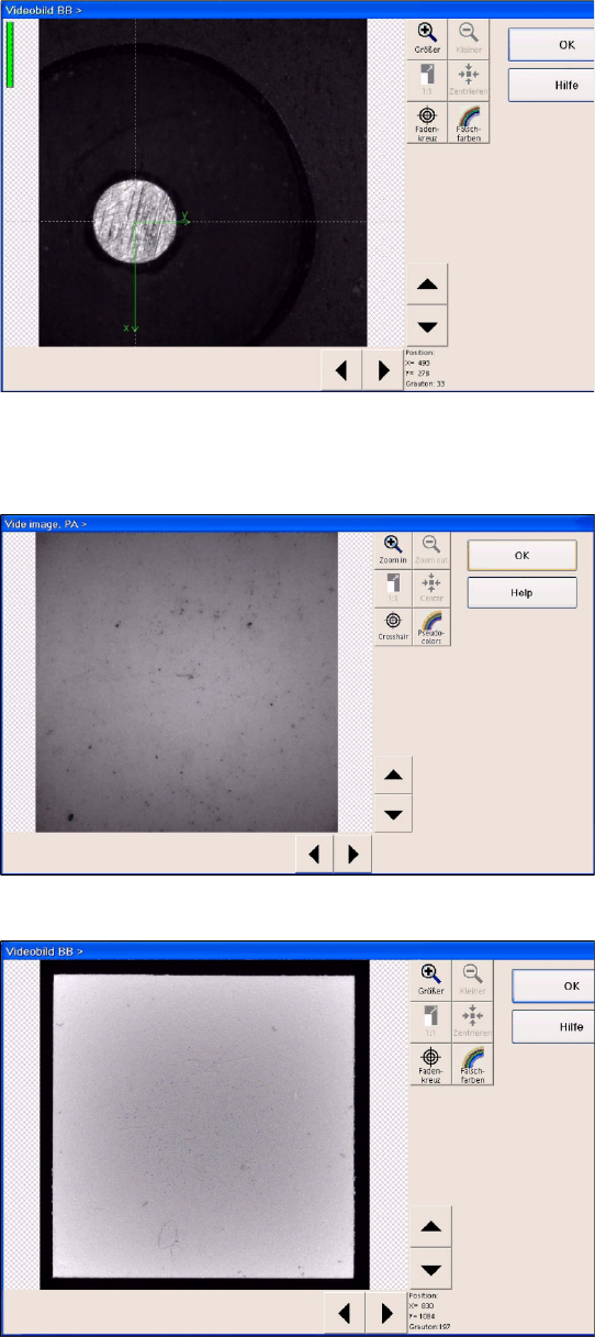
X Illumination calibration is now performed for
the PCB camera.
(see diagram of standard PCB camera)
X Tray position recognition is performed again.
X The gantry placement head picks up its
appropriate calibration tool for the component
camera.
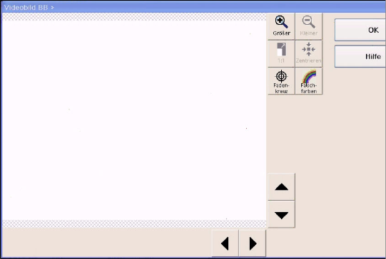
X The calibration tool is placed under or above
the respective component camera, the
balance process is performed and the
calibration tool is returned to where it was
picked up from.
(Here you can see a video image of the C&P6
component camera.
X The calibration process is repeated for the
cameras of the second gantry in the
placement area or for the second placement
head of the gantry.
Service Work
Placement Heads White Balance Process for SIPLACE Digital Vision Camera
102 Servicemanual (internal version) SIPLACE D Series
4.2.3.5 Continuation
X Once the calibration process has been completed, the technician needs to confirm this and then
have the carrier transported through to the output conveyor.
X When exiting SITEST, a message will be issued, informing you that machine data still need to be
saved. If you confirm this message, the values determined will be written to the camera EPROM.
X For report purposes, an XML file is created for each camera, in the
C:\SR-Daten\FCCS
folder.
This file is assigned a time stamp in its file name.
X In an ideal case, this file should be created before starting calibration.
However, the technician currently needs (SR/MC 603/604) to manually create these files in the
individual camera menus and select the respective storage paths (e.g.
C:\SR-Daten\FCCS
).
X From SR/MC SW version 605, the respective EPROM data is saved before and after the white
balance process, in a file in the
C:\SRDaten\FCCS
folder.
The file name contains the following:
- gantry name
- camera type name
- before/after calibration
- date stamp
Example:
Gantry_1_CameraID_25_after_FCCS_2008_06_06_14_01_28.xml
The illumination tool carrier is moved into
placement area 2 and the calibration process is
repeated, according to the machine configuration.
Here you can see a diagram of the FLIP-CHIP
camera option for the TWIN/P&P head.