SIPLACE D系列Servicemanual.pdf - 第106页
Service Wo rk Placement Heads White Balance Process for SIPLACE Digital Vision Camera 106 Servicemanual (internal ve rsion) SIPLACE D Series Can2ToPlane ="4" Can3ToPlane ="8" Can4ToPlane ="16&quo…

Service Work
White Balance Process for SIPLACE Digital Vision Camera Placement Heads
Servicemanual (internal version) SIPLACE D Series
105
DeadTime ="48800" />
<Shading Status ="0"
ShadingFactorX0 ="0.000000"
ShadingFactorX1 ="0.000000"
ShadingFactorX2 ="0.000000"
ShadingFactorX3 ="0.000000"
ShadingFactorX4 ="0.000000" />
<DefaultScale
x_nm ="26683" Default pixel size from construction
y_nm ="26710" Default pixel size from construction
StateX ="2" />
<CurrentScale
x_nm ="26741" Measured pixel size
y_nm ="26772" /> Measured pixel size
</Calibration>
<Statistics
NumberOfFlashes ="0"
NumberOfBootUps ="262" />
<Diagnostics
StateOfGSM ="4"
LastError ="00" />
<HardwareState
ChecksumEEPROM ="OK"
Selftest ="OK" />
- <SensorSpecificData
PixelScale ="124">
<FieldOfView
StartX ="204"
StartY ="8"
SizeX ="1220" No. of pixels (image points) per line in field of vision
SizeY ="1220" /> No. of pixels (image points) per column in field of vision
<Extended
MaxIllum ="10"
MinSleep ="10"
ModusTrigger ="4"
ModusTransmit ="0"
ModusEnable ="2"
ModusSense ="12"
ModusExposure ="5"
Can0ToPlane ="1"
Can1ToPlane ="2"
Parameter name Value of camera Comments

Service Work
Placement Heads White Balance Process for SIPLACE Digital Vision Camera
106 Servicemanual (internal version) SIPLACE D Series
Can2ToPlane ="4"
Can3ToPlane ="8"
Can4ToPlane ="16"
Can5ToPlane ="32"
FlashDelay ="0"
FinishDelay ="0"
ModusFlash ="0"
TriggerExposure ="20"
MaxExposure ="200" />
</SensorSpecificData>
</Sensorsystem>
Parameter name Value of camera Comments
Measuring Equipment and Tools
SIPLACE Axis Tester (SAT) [03002801-01]
Servicemanual (internal version) SIPLACE D Series
107
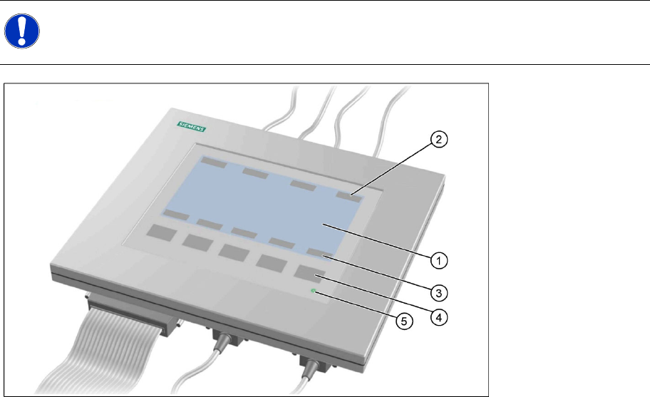
5 Measuring Equipment and Tools
5.1 SIPLACE Axis Tester (SAT) [03002801-01]
5-1: Axis tester - view from above
Legend
1. LCD display with 240 x 128 pixels, black-and-white display, with background illumination
The LCD display shows the menus and the recorded trigger, track and position signals. All relevant
parameters, such as
– Time basis,
– Time measurement values,
– Signal levels and
– Cursor positions with the corresponding time deviation values
are shown as alphanumerical data in the diagram of the measurement curves.
2. Dynamic function display of BNC socket arrangement on the LCD display
3. Dynamic function display of foil button arrangement on the LCD display
4. Five foil buttons for menu control
5. Green LED for displaying operation
NOTE:
The axis tester is designed for all machines with A363. This function is limited for machines with
A364.