SIPLACE D系列Servicemanual.pdf - 第15页
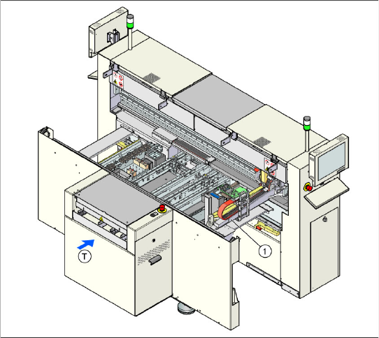
Overview SIPLACE D1 D-Series - General Servicemanual (internal version) SIPLACE D Series 15 3O v e r v i e w 3.1 D-Series - General 3.1.1 SIPLACE D1 3-1: SIPLACE D1 with one gantry Overvi ew 1 gantry 1 to 2 pla cemen…
Operational Safety
Preparations for Service Work Safety Instructions for the Compressed Air Supply
14 Servicemanual (internal version) SIPLACE D Series
2.2 Preparations for Service Work
Switch off the machine and secure it to prevent it being switched on again
X End all placement operations on the placement system.
X Disconnect the changeover table of the gantry concerned, if necessary.
X Wait until the operating system has shut down.
X Switch the placement system off at the main switch.
X Disconnect the machine from the power supply.
X Disconnect the placement system from the compressed air supply.
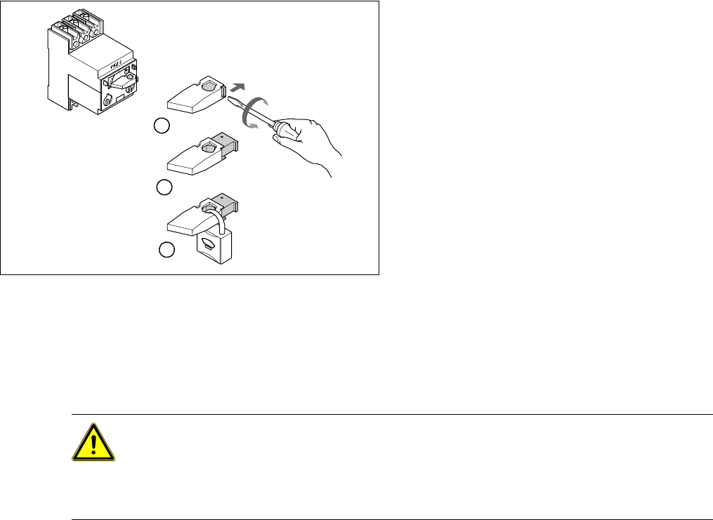
X Switch off the motor contactor in the power supply and secure it with a padlock.
Alternative: Attach warning signs.
If a machine can be locked, it must be. However, there are situations where energy isolating devices can
not accommodate locks. In these cases, the energy isolating devices must be tagged to warn employees
that the machine is de-energized for servicing. The sign must be securely fastened, it must be placed in
a position visible to all and it may only be removed by the person who attached it.
X Turn the operating lever (1) counterclockwise.
X Use the screwdriver to push the locking lug (2)
out of the operating lever (1).
X Secure the operating lever with a padlock (3).
1
3
2
CAUTION: Moving the gantry can damage the Collect&Place head:
When moving the gantry, observe the following:
X NEVER move the gantry by pushing with your hands against the Collect&Place head.
X NEVER push the gantry while the Z axis is lowered.
X ALWAYS take hold of the X axis base with your hands to move the gantry.
Overview
SIPLACE D1 D-Series - General
Servicemanual (internal version) SIPLACE D Series
15
3Overview
3.1 D-Series - General
3.1.1 SIPLACE D1
3-1: SIPLACE D1 with one gantry
Overview
1 gantry
1 to 2 placement heads
Pick&Place head: Twin or Highforce head
Collect&Place head:
– 12 segment C&P head (C&P12) or
– 6 segment C&P head (C&P6)
Component spectrum: 0201 to 200 mm x
125 mm, maximum component height: 25 mm
Performance: 14.000 components/h (with
C&P12)
Accuracy: 30 µm at 3 sigma (40 µm at
4sigma)
Placement force: 1 N to 30 N (with Highforce
head)
Locations:
– 90 x 8 mm (3 x 8 mm)
– 60 x 8 mm (3 x 8 mm) – with WPC-4
For more details, refer to the D1 specifications.
Overview
D-Series - General SIPLACE D2
16 Servicemanual (internal version) SIPLACE D Series
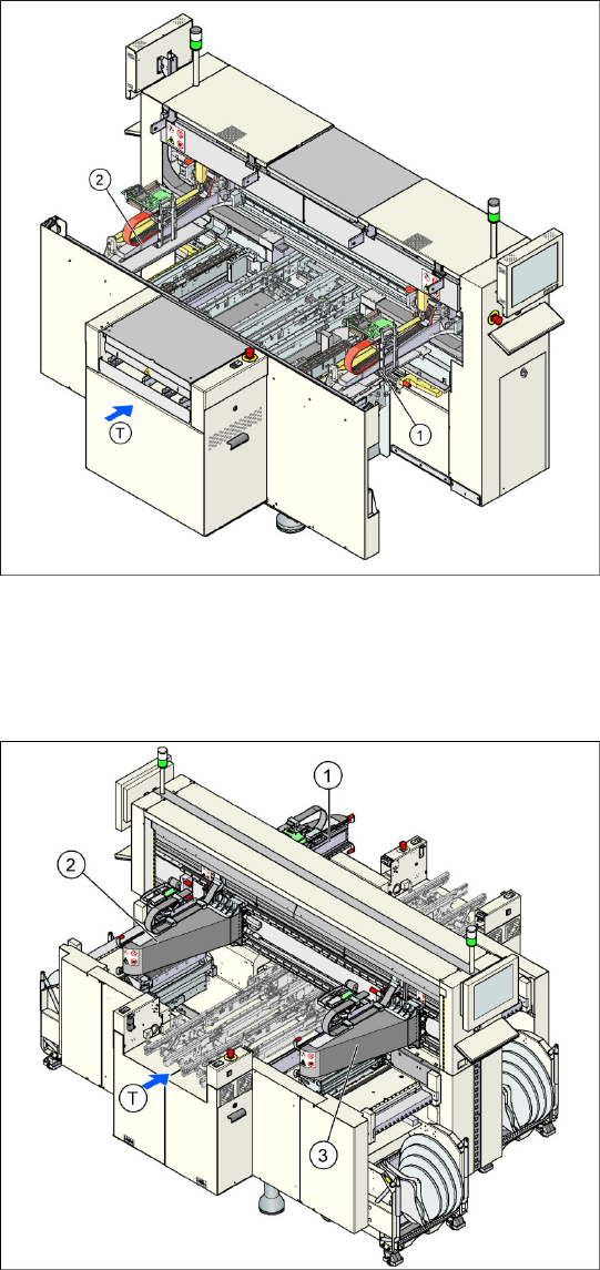
3.1.2 SIPLACE D2
3.1.3 SIPLACE D3
3-2: SIPLACE D2 with two gantries
Overview
2 gantries
2 placement heads
Collect&Place head:
– 2 x C&P12 or
– 2 x C&P6 or
– 1 x C&P6 and 1 x C&P12
Component spectrum: 01005 to 27 x 27 mm
Performance: up to 31.100 components/h
Accuracy: up to 52 µm at 3 sigma
Placement force: 2.4 N to 5 N
Locations:
– 90 x 8 mm (3 x 8 mm)
For more details, refer to the D2 specifications.
3-3: SIPLACE D3 with three gantries
Overview
3 gantries
3 placement heads
– 2 x C&P12 + 1 x Twin Head or
– 2 x C&P 6 + 1 x Twin Head or
– 1 x C&P12 + 1 x C&P6 + 1 x Twin or
Highforce head
Component spectrum 01005 – 85 x 85 mm /
125 x 10 mm max. 200 x 125 mm
Placement performance: up to 30,100
components per hour
Placement accuracy: up to 22 µm at 3 sigma
Placement force: 1 N to 30 N
5-part conveyor with bumper function
Locations:
– 144 x 8 mm (3 x 8 mm)
For more details, refer to the D3 specifications.