SIPLACE D系列Servicemanual.pdf - 第33页
Service Work D1/D2 Gantry Servicemanual (internal version) SIPLACE D Series 33 4.1.2.4 Replacing the Linear Mo tor - Primary Part [00333148-xx] Tools and Equipment Set of DIN 911 Allen keys Cable ties Belt tension …
Service Work
Gantry D1/D2
32 Servicemanual (internal version) SIPLACE D Series
X Remove the blue supports. Remove the magnet cover to do this.
X Loosen the 8 or 16 M6 x 14 hexagon socket-head screws of the permanent magnet (1).
X Lift the permanent magnet and place it on a clean, nonmagnetic surface (such as a plank of wood).
X Move the gantry to a position which gives you good access and pull the magnet cover out from under
the Y motor.
Installation
Settings
X Check the axis dynamics of the drives removed.
CAUTION: Permanent magnets
When permanent magnets are placed on a magnetic surface (e.g. iron, nickel or steel), be
extremely careful not to catch your hands or fingers between the surface and the permanent
magnet. If you do, you will not be able to lift the magnet from the surface on your own.
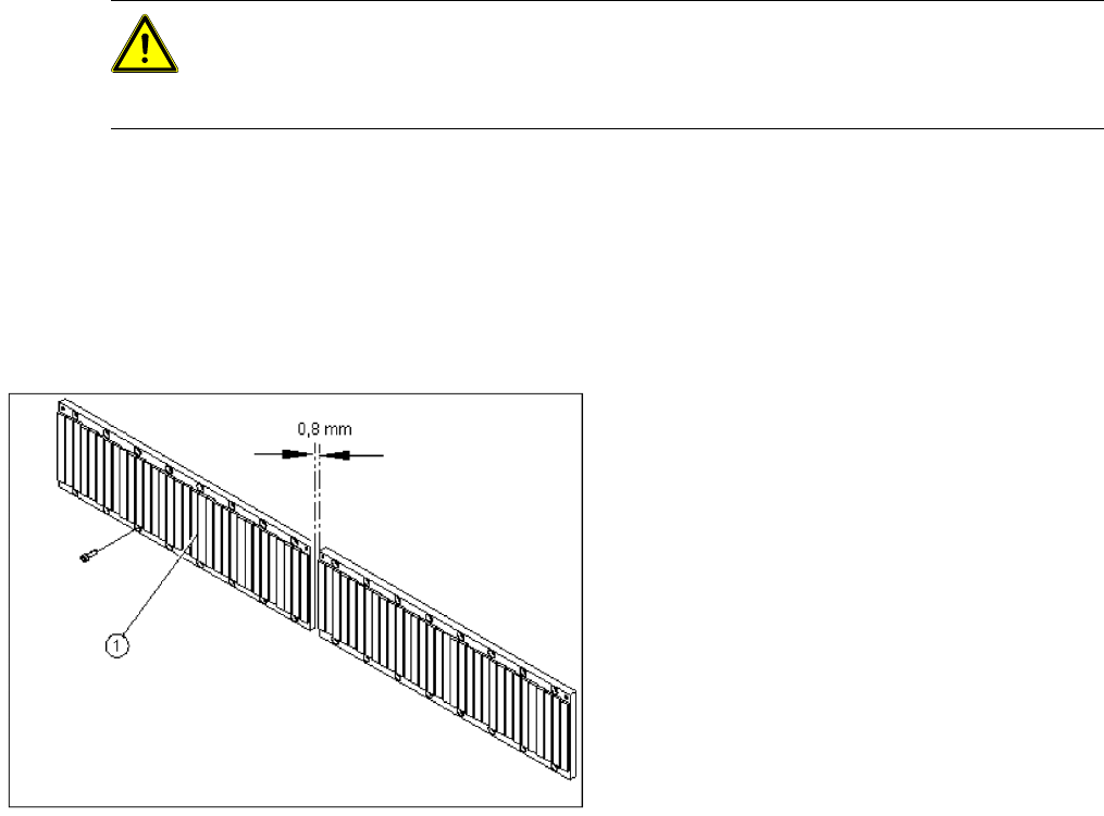
X Fit the permanent magnets (4 or 16 M6 x 12
hexagon socket-head screws). The space at
the bottom must be 0.8 mm. Use the
appropriate feeler gauge or plastic strip to help
you. A gap of approx. 0.8 mm should be
between the magnet plates.
X Fit the cover strips on the crossbeam above
the gantry concerned (3 M6 x 8 hexagon
socket-head screws).
Service Work
D1/D2 Gantry
Servicemanual (internal version) SIPLACE D Series
33
4.1.2.4 Replacing the Linear Motor - Primary Part [00333148-xx]
Tools and Equipment
Set of DIN 911 Allen keys
Cable ties
Belt tension measuring device TSM [00326015-xx]
"Measuring belt tensions" operating instructions
SITEST program
Parts
Linear motor - primary part [00333148-xx]
Removing the permanent magnets
X Switch off the machine and secure it to prevent unauthorized reactivation.
X Move the relevant gantry so that you can access the required permanent magnet:
Gantry 1 D1/D2: Dismantle the left permanent magnet segment of the Y-axis.
Gantry 2 D2: Dismantle the right permanent magnet segment of the Y-axis.
X Remove the black cover strips on the crossbeam above the gantry concerned (3 M6 x 8 hexagon
socket-head screws).
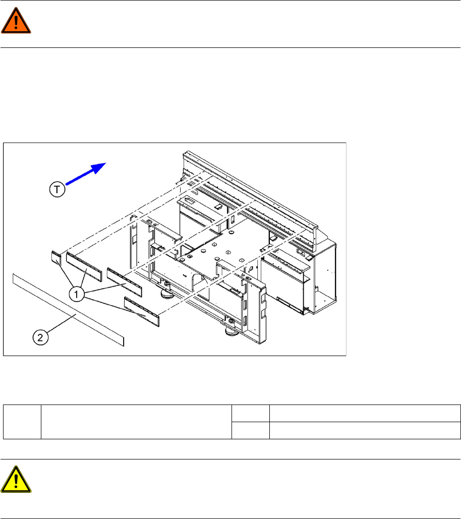
4-9: Position of the permanent magnets for the Y linear drive (D1/D2)
Legend
DANGER: POWERFUL MAGNETIC FIELD
Always follow the special safety instructions when working in the vicinity of powerful magnetic
fields.
1 Permanent magnets for Y linear drive of
gantries 1 and 2
2 Cover plate
T Transport direction
CAUTION:
Permanent magnets
When permanent magnets are placed on a magnetic surface (e.g. iron, nickel or steel), be
extremely careful not to catch your hands or fingers between the surface and the permanent
magnet. If you do, you will not be able to lift the magnet from the surface on your own.
Service Work
Gantry D1/D2
34 Servicemanual (internal version) SIPLACE D Series
X Remove the blue supports. Remove the magnet cover to do this.
X Loosen the 8 or 16 M6 x 14 hexagon socket-head screws of the permanent magnet (1).
X Lift the permanent magnet and place it on a clean, nonmagnetic surface (such as a plank of wood).
X Move the gantry to a position which gives you good access and pull the magnet cover out from under
the Y motor.
Removing the primary part of the linear motor
X Fit the X axis motor unit as described in section (4.1.2.5 Replacing the X Motor Unit [00333167-xx]
J
37 ) .
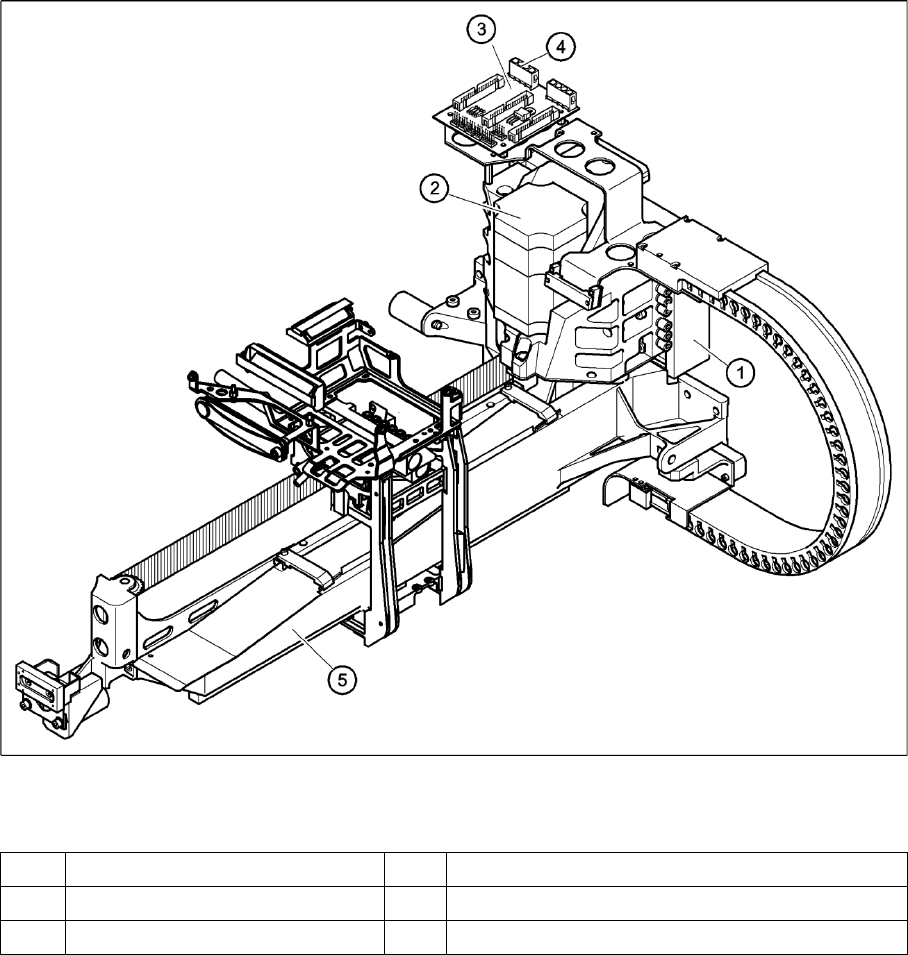
4-10: Replacing the linear motor primary part (D4)
Legend
(1) Linear motor - primary part (4) Socket X4 for the connecting cable of the primary part
(1) X-axis motor unit (5) Gantry
(5) X/Y distributor