SIPLACE D系列Servicemanual.pdf - 第35页
Service Work D1/D2 Gantry Servicemanual (internal version) SIPLACE D Series 35 4-11: Replacing the linear motor primary part ( D4) Legend 1. X-axis motor unit 2. Linear moto r - primary part 3. 9 x M5x20 hexa gon socket-…
Service Work
Gantry D1/D2
34 Servicemanual (internal version) SIPLACE D Series
X Remove the blue supports. Remove the magnet cover to do this.
X Loosen the 8 or 16 M6 x 14 hexagon socket-head screws of the permanent magnet (1).
X Lift the permanent magnet and place it on a clean, nonmagnetic surface (such as a plank of wood).
X Move the gantry to a position which gives you good access and pull the magnet cover out from under
the Y motor.
Removing the primary part of the linear motor
X Fit the X axis motor unit as described in section (4.1.2.5 Replacing the X Motor Unit [00333167-xx]
J
37 ) .
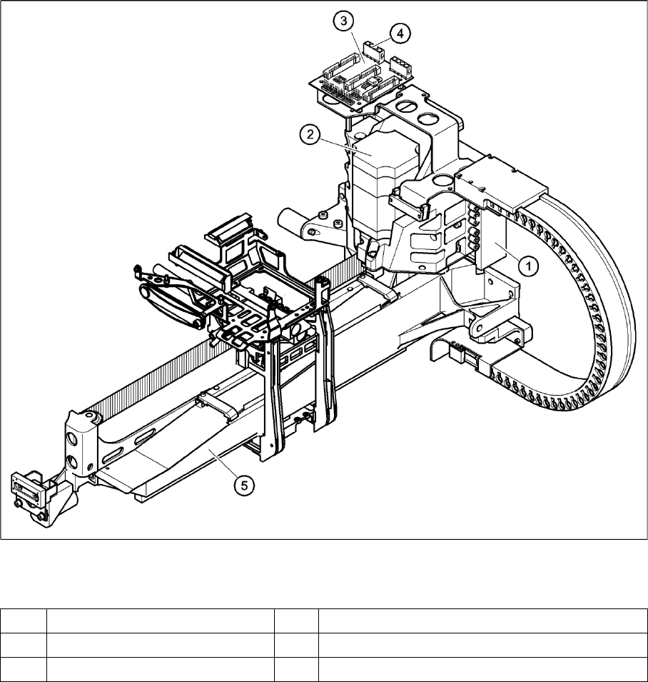
4-10: Replacing the linear motor primary part (D4)
Legend
(1) Linear motor - primary part (4) Socket X4 for the connecting cable of the primary part
(1) X-axis motor unit (5) Gantry
(5) X/Y distributor
Service Work
D1/D2 Gantry
Servicemanual (internal version) SIPLACE D Series
35
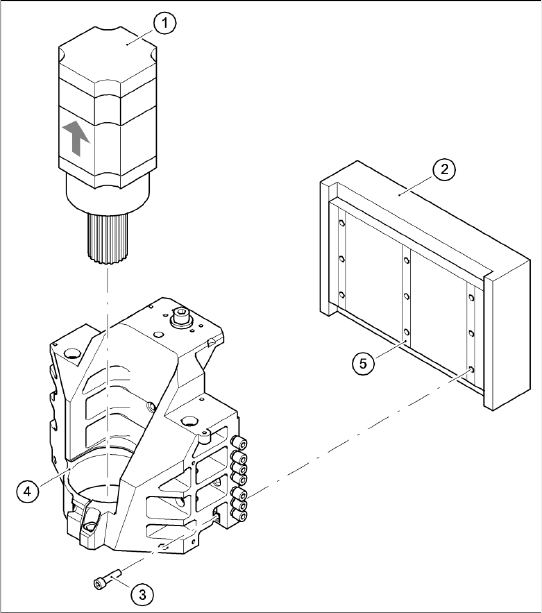
4-11: Replacing the linear motor primary part (D4)
Legend
1. X-axis motor unit
2. Linear motor - primary part
3. 9 x M5x20 hexagon socket-head screws
4. Motor bracket with press-fit connection
(pneumatic system)
5. Lockrail
X Loosen the nine M5 x 20 hexagon socket-
head screws (3) and remove the primary part
(2).
X Make sure that the lock rails will not drop.
Service Work
Gantry D1/D2
36 Servicemanual (internal version) SIPLACE D Series
Installing the primary part of the linear motor
Settings
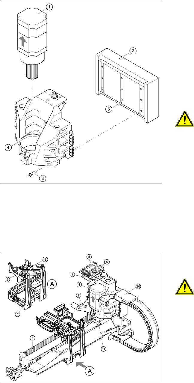
4-12: Replacing the linear motor primary part (D4)
X Fit scotch tape to the lower edge of the primary
part of the linear motor, so that the lockrails (5)
do not fall out during assembly.
X Push in the primary part from the side.
X Fasten the primary part (2) with the nine M5 x
20 hexagon socket-head screws (3) to the
motor bracket (4).
X Make sure that the primary part is aligned in
parallel to the permanent magnet.
X Fit the X axis motor unit as described in sec-
tion (4.1.2.5 Replacing the X Motor Unit
[00333167-xx]
J
37 ) .
X Fix all the cables with cable ties.
CAUTION:
X Make sure that the cables are firmly
seated. Otherwise, the high
acceleration forces may cause the
cable to slip out of position and shear
through.
X Fit the permanent magnets (4 or 16 M6 x 12
hexagon socket-head screws). The space at
the bottom must be 0.8 mm. Use the
appropriate feeler gauge or plastic strip to help
you. A gap of approx. 0.8 mm should be
between the magnet plates.
X Fit the cover strips on the crossbeam above
the gantry concerned (3 M6 x 8 hexagon
socket-head screws).
4-13: Replacing the X-axis motor unit (D4)
X Use the belt tension measuring device to set
the X-axis toothed belt tension to 44 Hz + /-1
Hz.
CAUTION:
X Do not overstretch the toothed belt
when adjusting the belt tension.
X Secure the M4x35 hexagon socket-head
screw (2) with the locknut (8).
X Check the axis dynamics of the drives
removed.