SIPLACE D系列Servicemanual.pdf - 第39页
Service Work D1/D2 Gantry Servicemanual (internal version) SIPLACE D Series 39 Installing the X-axis motor unit X When using SIPLACE D1 machines, the h eat sink from the old X motor needs to be fitted onto the new one. F…

Service Work
Gantry D1/D2
38 Servicemanual (internal version) SIPLACE D Series
X Switch off the machine and secure it to prevent unauthorized reactivation.
1 gantry D1 (2 gantries D2)
X Remove the cover strip on the crossbeam above the gantry concerned:
Unplug the fan cable. The fan is fixed to the cover strip.
Remove the cover strip (3 M6x8 hexagon socket-head screws).
X Cut the cable ties holding the X-axis motor cable.
X Remove the cable clamp for the flat ribbon cable (11).
X Disconnect all the plugs from the X/Y distributor (5).
X Remove the X/Y distributor (5).
X Remove the board holder for the X/Y distributor (9).
X Remove the cable holders (10) on the trailing cable.
X To relax the toothed belt (3), proceed as follows:
Loosen the locknut (8) and
Turn the hexagon socket-head screw (2) counterclockwise.
X Loosen the two M6 x 14 hexagon socket-head screws (7) fixing the X motor unit (4).
X Pull the X motor unit (4) up and out,
X at the same time pushing the board holder slightly to the side.
DANGER: POWERFUL MAGNETIC FIELD
X Always follow the special safety instructions when working in the vicinity of powerful magnetic
fields.
Service Work
D1/D2 Gantry
Servicemanual (internal version) SIPLACE D Series
39
Installing the X-axis motor unit
X When using SIPLACE D1 machines, the heat sink from the old X motor needs to be fitted onto the
new one. For details, consult the corresponding retrofitting guide [00195618-xx].
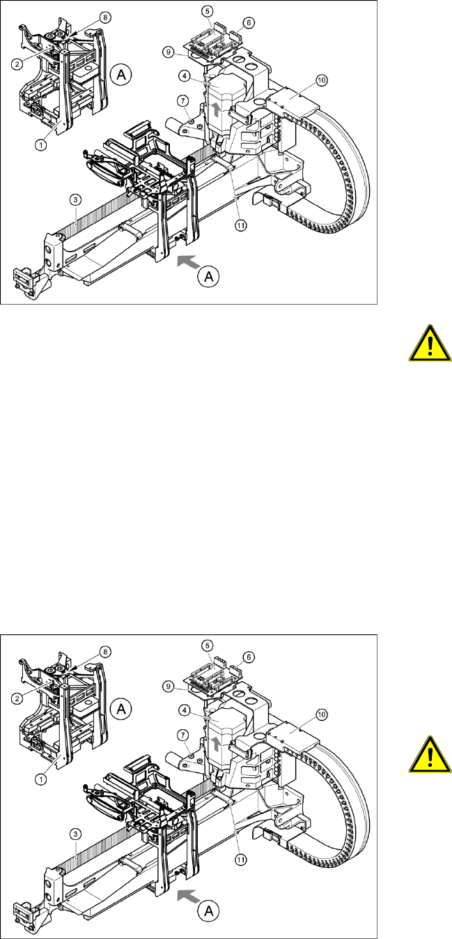
4-15: Replacing the X motor unit (D4 shown as example)
1 gantry D1 (2 gantries D2)
X Carefully insert the X motor unit (4) as far as
the stop,
making sure that you do not damage the
toothed belt. The motor cable points towards
the permanent magnets of the linear drive.
X Fix the X motor unit into place with the two
hexagon socket-head screws (7).
X Fit the cable holders for the trailing cable (10).
X Fit the board holder (9).
X Fit the X/Y distributor (5).
X Connect all plugs to their sockets on the X/Y
distributor (5).
X Fix the flat ribbon cable with the cable clamp
(11).
X Fix all the cables with cable ties.
CAUTION:
Make sure that the cables are firmly
seated. Otherwise, the high
acceleration forces may cause the
cable to slip out of position and shear
through.
X Tension the X toothed belt with the hexagon
socket-head screw (2).
X Use the three M6 x 8 hexagon socket-head
screws to fit the cover strip to the crossbeam,
above the gantry concerned.
X Connect the cable of the fan motor to the
socket.
4-16: Replacing the X motor unit (D4 shown as example)
X Push the head mount (1) towards the X axis
motor unit, as far as the stop on the
elastomeric spring.
X Turn the hexagon socket-head screw (2) to set
the belt tension to 44 Hz +/-1 Hz.
CAUTION:
Do not overstretch the toothed belt
when adjusting the belt tension.
X Secure the hexagon socket-head screw (2)
with the locknut (8).
Service Work
Gantry D3
40 Servicemanual (internal version) SIPLACE D Series
4.1.3 D3
4.1.3.1 Replacing the X Axis Scale [03003745]
Special equipment
Scriber to loosen the scale
Ethanol
Protective gloves
Double-sided adhesive strip - Scotch Y-9460 [00343774-xx]
Protective sheet 12mm wide [00378511-xx]
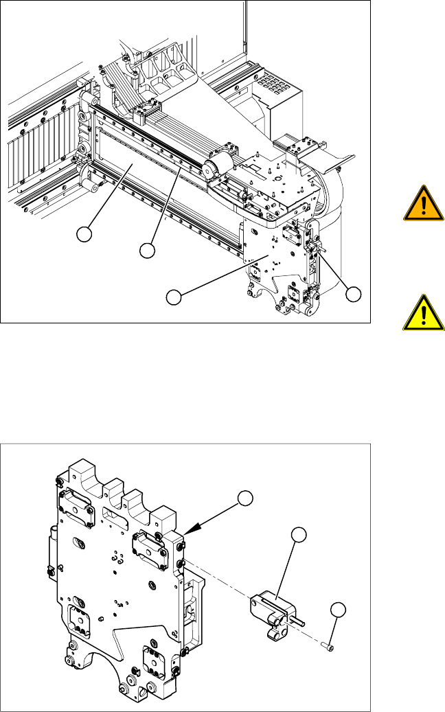
Overview
Removing the read head
Legend
1. Head plate
2. X axis scale (fixed with adhesive)
3. Permanent magnets
4. X axis read head
X Move the head plate (2) to a suitable position
so that you can easily access the X axis scale
(1) from all sides.
WARNING: STRONG MAGNETIC
FIELDS!
Always follow the special safety
instructions when working in the vicinity
of powerful magnetic fields, caused by
the permanent magnets (3).
ATTENTION: Do not dismantle the
head plate!
To guarantee accuracy, make sure that
you do not dismantle the head plate (2).
X Dismantle the read head (4).
4
1
3
2
Legend
1. Head plate - front view
2. Read head
3. 3 x fastening screws
X Loosen the three screws (3) fastening the read
head (2) of the X axis and carefully lift off the
read head.
X Temporarily fasten the read head in a suitable
position.
3
1
2