SIPLACE D系列Servicemanual.pdf - 第40页
Service Wo rk Gantry D3 40 Servicemanual (internal ve rsion) SIPLACE D Series 4.1.3 D3 4.1.3.1 Replacing th e X Axis Scale [03003745] Special equipment Scriber to lo osen the sc ale Ethanol Protective gloves Doub…
Service Work
D1/D2 Gantry
Servicemanual (internal version) SIPLACE D Series
39
Installing the X-axis motor unit
X When using SIPLACE D1 machines, the heat sink from the old X motor needs to be fitted onto the
new one. For details, consult the corresponding retrofitting guide [00195618-xx].
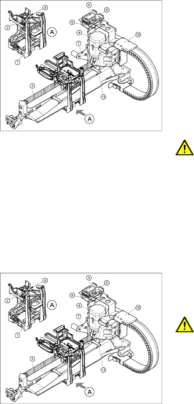
4-15: Replacing the X motor unit (D4 shown as example)
1 gantry D1 (2 gantries D2)
X Carefully insert the X motor unit (4) as far as
the stop,
making sure that you do not damage the
toothed belt. The motor cable points towards
the permanent magnets of the linear drive.
X Fix the X motor unit into place with the two
hexagon socket-head screws (7).
X Fit the cable holders for the trailing cable (10).
X Fit the board holder (9).
X Fit the X/Y distributor (5).
X Connect all plugs to their sockets on the X/Y
distributor (5).
X Fix the flat ribbon cable with the cable clamp
(11).
X Fix all the cables with cable ties.
CAUTION:
Make sure that the cables are firmly
seated. Otherwise, the high
acceleration forces may cause the
cable to slip out of position and shear
through.
X Tension the X toothed belt with the hexagon
socket-head screw (2).
X Use the three M6 x 8 hexagon socket-head
screws to fit the cover strip to the crossbeam,
above the gantry concerned.
X Connect the cable of the fan motor to the
socket.
4-16: Replacing the X motor unit (D4 shown as example)
X Push the head mount (1) towards the X axis
motor unit, as far as the stop on the
elastomeric spring.
X Turn the hexagon socket-head screw (2) to set
the belt tension to 44 Hz +/-1 Hz.
CAUTION:
Do not overstretch the toothed belt
when adjusting the belt tension.
X Secure the hexagon socket-head screw (2)
with the locknut (8).
Service Work
Gantry D3
40 Servicemanual (internal version) SIPLACE D Series
4.1.3 D3
4.1.3.1 Replacing the X Axis Scale [03003745]
Special equipment
Scriber to loosen the scale
Ethanol
Protective gloves
Double-sided adhesive strip - Scotch Y-9460 [00343774-xx]
Protective sheet 12mm wide [00378511-xx]
Overview
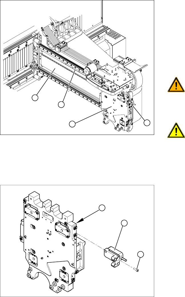
Removing the read head
Legend
1. Head plate
2. X axis scale (fixed with adhesive)
3. Permanent magnets
4. X axis read head
X Move the head plate (2) to a suitable position
so that you can easily access the X axis scale
(1) from all sides.
WARNING: STRONG MAGNETIC
FIELDS!
Always follow the special safety
instructions when working in the vicinity
of powerful magnetic fields, caused by
the permanent magnets (3).
ATTENTION: Do not dismantle the
head plate!
To guarantee accuracy, make sure that
you do not dismantle the head plate (2).
X Dismantle the read head (4).
4
1
3
2
Legend
1. Head plate - front view
2. Read head
3. 3 x fastening screws
X Loosen the three screws (3) fastening the read
head (2) of the X axis and carefully lift off the
read head.
X Temporarily fasten the read head in a suitable
position.
3
1
2
Service Work
D3 Gantry
Servicemanual (internal version) SIPLACE D Series
41
Removing the scale
X Place the new scale on a clean work surface.
X Attach the double-sided adhesive tape to the back of the new scale. The surface to be fixed down
must be clean and free of grease.
Installation of scale
X Insert the new scale behind the head plate.
X Attach the new scale exactly to the lay-on edge on the gantry.
X Pull part of the cover strip off the adhesive strip and place the front end of the scale on the marked
position. The scale must be positioned at the lay-on edge.
X Now pull away the cover strip „piece by piece“ and firmly fix the scale (to about halfway along the
gantry).
X Move the head plate so that you can fix the rest of the scale.
X Press the scale down with a soft, clean cloth.
X Carefully pull off the cover strip.
X Wipe a little ethanol over the scale to remove any adhesive residues or dirt.
X Fit the read head. This procedure is described in Chapter "Replacing the X Axis Read Head".
See also:
J
4.1.3.7 Replacing the X Axis Incremental Encoder [03020588S-xx] [
J
67]
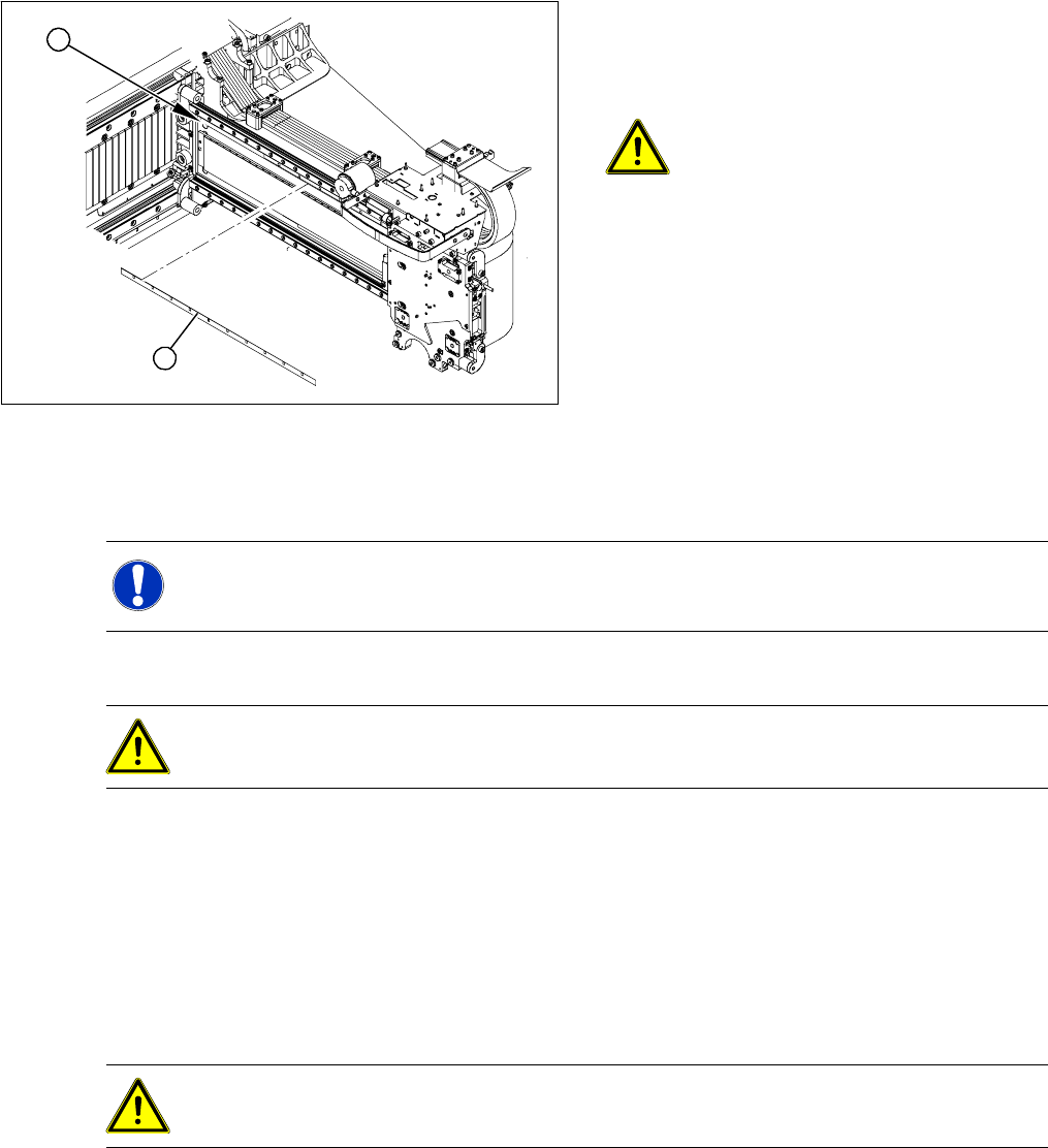
X Mark the original position (1) of the scale (2)
with a scribing iron. This ensures that the new
scale can be fixed in the exact position to the
right and left end stop.
ATTENTION: Do not damage the
gantry.
Make sure that the gantry coating is not
damaged.
X Carefully lever the scale upwards on one side
with the scriber and then gently extract the
scale.
X Remove any adhesive residues with ethanol.
The surface to be fixed down must be clean
and free of grease.
2
1
NOTE: Cover strip on scale
X A cover strip protects the front of the scale. Remove this cover strip AFTER installation.
ATTENTION: Take care when handling the incremental scale.
Do not touch the incremental tracks with bare fingers.
ATTENTION: Make sure that no blisters or uneven areas are formed.
If this does occur, the scale must be removed and replaced with a new scale.