SIPLACE D系列Servicemanual.pdf - 第55页
Service Work D3 Gantry Servicemanual (internal version) SIPLACE D Series 55 Removal Legend 1. Trailing unit interface gantry 2. Pneumatic for vacu um pump (option) 3. Mount for trailing cable 4. Gantry interface X Loosen…
Service Work
Gantry D3
54 Servicemanual (internal version) SIPLACE D Series
Version 2 after B-079
See also:
J
Preparing the Trailing Cable [
J
50]
J
Handling the Hose Unlocking Tool [03047090-xx] [
J
48]
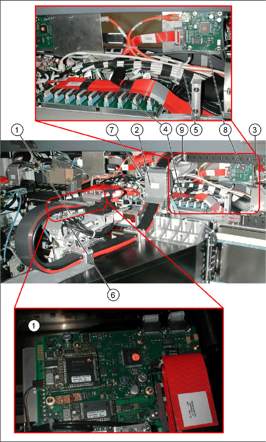
Legend
1. Vision board spread spectrum (VBSX)
assembly [03054634-xx]
2. Trailing cable console
3. Power track chain
4. Trailing unit interface gantry
5. Pneumatic hoses to the pneumatic distributor
(in the machine base)
6. Gantry distributor
7. Gantry interface
8. Vision hotlink adapter VHA assembly
[03054633-xx]
9. Connection piece for cooling tubes to Y motor
Service Work
D3 Gantry
Servicemanual (internal version) SIPLACE D Series
55
Removal
Legend
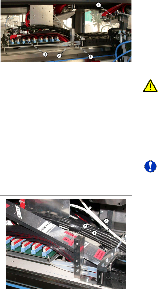
1. Trailing unit interface gantry
2. Pneumatic for vacuum pump (option)
3. Mount for trailing cable
4. Gantry interface
X Loosen the flat ribbon cable on the trailing unit
interface gantry (1). Take care not to lose the
brackets for the press-fit connections. They
could fall out and be lost.
X Remove cable ties where necessary.
ATTENTION:
Note the order in which the terminal
connections are arranged.
X Label the press-fit connections to the
flat ribbon cables, for easier
reconnection later.
X Remove the necessary cable ties at the gantry
interface (4) and disconnect the flat ribbon
cable.
X Disconnect the motor, proximity switches,
incremental encoder and temperature sensor
cables from the gantry interface (4) .
NOTE: Refitting the gantry interface
board.
The gantry interface board is installed
on the mount of the new trailing cable.
To sever the pneumatic hoses, which lead to the
pneumatic distributor inside the machine base,
proceed as follows:
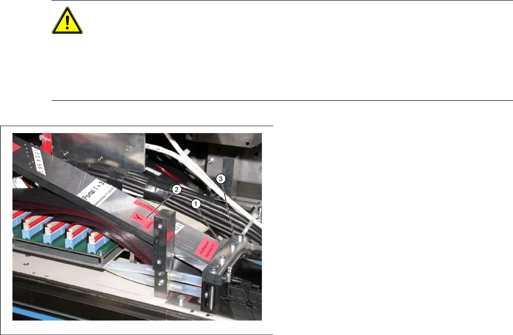
X Place the gauge (1) on the mount (3).
X Use the gauge to label the hoses at the Y hose
mark (2).
Service Work
Gantry D3
56 Servicemanual (internal version) SIPLACE D Series
CAUTION: Before cutting the pneumatic hoses
X Label the order of pneumatic hoses (from 1 to 7 – inside to outside). This is important to
ensure that the hoses are then correctly connected again after cutting.
X During cutting, make sure that the pneumatic hoses do not fall into the machine base. Secure
them accordingly.
X Make sure that you use the correct gauge for your gantries and that you do not cut the
pneumatic hoses too short.
X Loosen the screws fastening the trailing cable
mount (3) .
X If the option "Vacuum pump" is available,
loosen the pneumatic hoses (2) and follow the
instructions in the
Retrofitting Guide for
Vacuum Pumps
[0019508901].
X Secure the end of the trailing cable (with cable
ties) in the machine to prevent it hanging
loosely and damaging other machine
components.