SIPLACE D系列Servicemanual.pdf - 第58页
Service Wo rk Gantry D3 58 Servicemanual (internal ve rsion) SIPLACE D Series Inst allation CAUTION: Handle the new trailing cable with care and enlist the help of a second person. Make sure that the flat ribbon ca ble a…
Service Work
D3 Gantry
Servicemanual (internal version) SIPLACE D Series
57
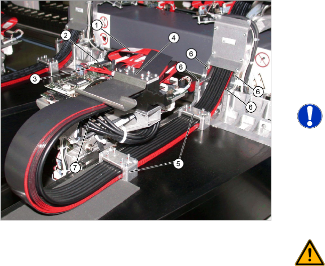
X Loosen the flat ribbon cable (1) at the head
board (2).
X Loosen the camera cable (3) at the head
board (2).
X Undo the screws fastening the X trailing cable
clamp (4) and the two clamps (5) on the back
of the gantry.
NOTE: Clamp remains intact
X Only loosen the fastening screws.
The clamps for the flat ribbon cable
remain in place.
X Mark the installation position of the
contact disks and spacer bolts and
take care not to lose them. These will
need to be correctly replaced later.
X Remove the hoses from the pneumatic
distributor (7).
WARNING: Risk of injury to hands
X Use the hose unlocking tool to
remove the hoses [03047090-xx].
X Undo the 4 screws (6) fastening the trailing
cable console and carefully remove the
complete trailing cable from the machine. The
fastening screws have been secured with
Loctite.
X When you replace an old trailing cable with a
new one, you also need to remove the hotlink
card (including metal fixtures) and the Vision
board spread spectrum.
Service Work
Gantry D3
58 Servicemanual (internal version) SIPLACE D Series
Installation
CAUTION:
Handle the new trailing cable with care and enlist the help of a second person. Make sure that
the flat ribbon cable and the pneumatic hoses are not rubbed against any parts or folded.Look
out for sharp edges.
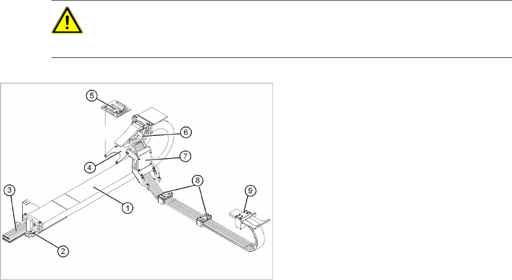
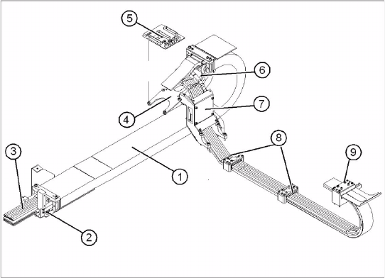
Legend
1. Complete trailing cable unit
2. Mount
3. Pneumatic hoses (shorten to optimum length
with gauge)
4. Gantry interface bracket
5. Gantry interface
6. Connection piece for cooling tubes to Y motor
7. Trailing cable console
8. Clamp at back of gantry
9. X trailing cable clamp
X If you replace a trailing cable which is of
version 1 from B-079-B with a trailing cable
which is of version 2 after B-079-B , first
replace the new "Vision hotlink adapter VHA
assembly" [03054633-xx] and the "Vision
board spread spectrum (VBSX) assembly."
[03054634-xx].
X Carefully insert the new trailing cable (1) into
the prescribed position. Make sure you do not
twist it.
X Temporarily fasten the ends to the machine
base (by tying them etc.).
X Fit the gantry interface board (5) onto the
holder (4) of the new trailing cable.
Service Work
D3 Gantry
Servicemanual (internal version) SIPLACE D Series
59
X Loosely fasten the trailing cable console (7)
with a screw.
X Clean the trailing cable contact surface on the
machine base with a dry cloth.
X Starting from the trailing cable console (7), run
all cables and hoses to the appropriate
connections:
X Reconnect all electrical connections at the
head board. Observe the correct connector
assignment.
X Reestablish all connections to the hotlink card
and the Vision board spread spectrum.
X Reconnect all compressed air connections at
the pneumatic distributor. Observe the correct
connector assignment.
X The pneumatic hoses need to be shortened to
the optimum length, with the help of the gauge.
See also section ( Preparing the Trailing Cable
J
50 ) . They must engage firmly but should
not fold.
X Loosely screw in the clamps (8) and (9).
X Check that the power track chain can run
along the top of the machine base without
obstruction. Move the Y axis back and forth to
check this.
X If necessary, correct at the trailing cable
console (7) and at the clamps (8) and (9).
X Fix the two clamps (8) and (9) and the trailing
cable console (7). Use Loctite 241 to secure
them.
X Tighten the fastening screws for the trailing
cable console (7) crosswise.