SIPLACE D系列Servicemanual.pdf - 第66页
Service Wo rk Gantry D3 66 Servicemanual (internal ve rsion) SIPLACE D Series 4.1.3.6 Replacing th e Y Linear Motor - Primary Part Item number Linear motor Y drive, complete (D3, X series) [03013 459-xx] Removal Instal…
Service Work
D3 Gantry
Servicemanual (internal version) SIPLACE D Series
65
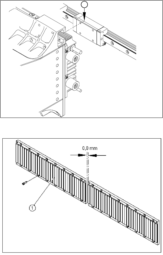
X With the aid of a 1/100 plastic thickness
gauge, check the gap between the portal
contact edge and the guide trolley (1). The
gantry must lie flush with the guide trolley,
leaving no room in-between for the thickness
gauge.
X If this is not the case, dismantle the gantry and
clean the contact surfaces again thoroughly
(with the dressing stone).
1
X Fit the magnetic strip (1).
X Make sure that there is a gap of 0.8 mm
between the two magnetic strips.
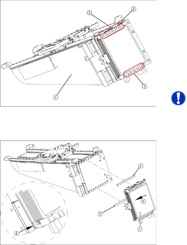
X Install the blue covers.
X Install the cover plate for the magnet.
X Install the trailing cable.
X Install the PCB camera.
X Reconnect to the electrical and pneumatic
systems.
X Fasten all electrical leads and pneumatic
hoses to the correct points.
X Install all dismantled modules, covers and
cover plates.
Service Work
Gantry D3
66 Servicemanual (internal version) SIPLACE D Series
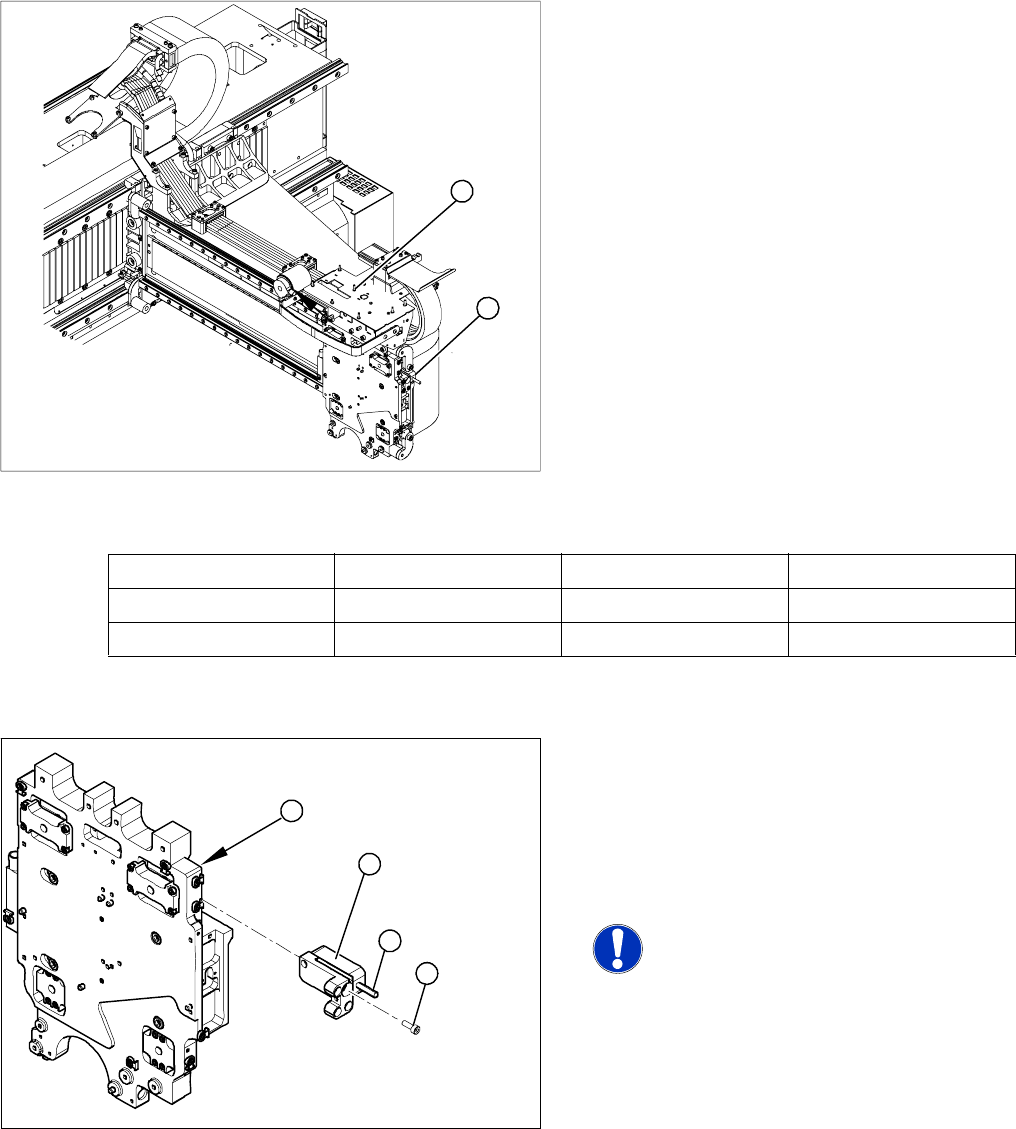
4.1.3.6 Replacing the Y Linear Motor - Primary Part
Item number
Linear motor Y drive, complete (D3, X series) [03013459-xx]
Removal
Installation
Settings
X Check the axis dynamics of the drives removed.
X Dismantle the gantry (see section (4.1.3.5 Re-
placing Gantries
J
61 ) ) and put it in a
suitable place (1).
X Remove the cable ties holding the connection
cable.
X Remove the proximity switch mount (2) and
proximity switches.
X Undo the 16 fastening screws (3). Make sure
you do not lose the insulating plates
underneath the screws. These must be
replaced after completing service work.
NOTE:
The fastening screws have been
secured with locking varnish (Loctite
241).
X Loosely fasten the new Y drive (1) with the
screws and insulating plates (2) provided. Use
Loctite 241 to secure it.
X Press the motor upwards, within the tolerance
of the drilling (3). if you do not do this, the
motor could lie on the bottom guides. Now
tighten the two center screws.
X Make sure that the ends of the insulation
plates (4) are not protruding (these plates are
not symmetrically centered). If necessary,
press these back in with a suitable tool (e.g.
screwdriver).
X Then tighten all 16 fastening screws with the
aid of a torque wrench (first in the center, then
at the top and lastly at the bottom) (5.5 N).
X Install the proximity switch mount and
proximity switches.
X Fasten the connection cable so that it will not
be in the way when installing the gantry.
X Install the gantry and the trailing cable.
Service Work
D3 Gantry
Servicemanual (internal version) SIPLACE D Series
67
4.1.3.7 Replacing the X Axis Incremental Encoder [03020588S-xx]
Overview
Press-fit connections
Removal
Legend
1. Installation point for head interface and Vision
board
2. Incremental encoder position
X Unplug the incremental encoder press-fit
connection (2) from the head interface (1).
1
2
Assembly Gantry Board Terminals
X axis incremental encoder Gantry 1 (C&P head ) Head interface 03000901 X15ac
X axis incremental encoder Gantry 2 (Twin Head) Head interface 03000901 X15bc
Legend
1. Head plate - front view
2. Incremental encoder
3. 3 x fastening screws
4. Grub screw (secured with Loctite No. 241)
NOTE: Grub screw on the
incremental encoder
If the incremental encoder is installed
on the head plate of a CFK 04 or 06
gantry, the grub screw is without
function. Do not loosen or tighten this
grub screw.
X Unthread the connection cable as far as the
incremental encoder (2).
X Loosen the three screws (3) fastening the
incremental encoder (2) of the X axis and
carefully lift off the incremental encoder.
3
4
1
2