SIPLACE D系列Servicemanual.pdf - 第70页
Service Wo rk Gantry D3 70 Servicemanual (internal ve rsion) SIPLACE D Series X Unplug the proximity switch cable (2) and pull it forwards, out of the head mo unt. X Undo the 8 screws (4 x at fr ont/ 4x at back) fastenin…
Service Work
D3 Gantry
Servicemanual (internal version) SIPLACE D Series
69
4.1.3.8 Replacing the X Drive (Primary) [03039726-xx]
Required equipment
Service Pack X drive (00377437-xx) for SIPLACE HF/X machines
–X drive
– 4 x dismantling screws
– 8 x lock screws (M4x60)
– Templates for Twin Head and DLM2
– 6 grub screws M4x6-ST
– Plastic thickness gauge 0.4 mm (approx. 50 cm long and 10 cm wide)
– Foam rest 500 mm x 50 mm x 20 mm
Xenon flashlight (non-magnetic)
Torque wrench with socket-head adapter
Loctite 241
Removal
NOTE:
The service pack for the X drive 00375245-01 only fits HF machines up to machine number
A219.
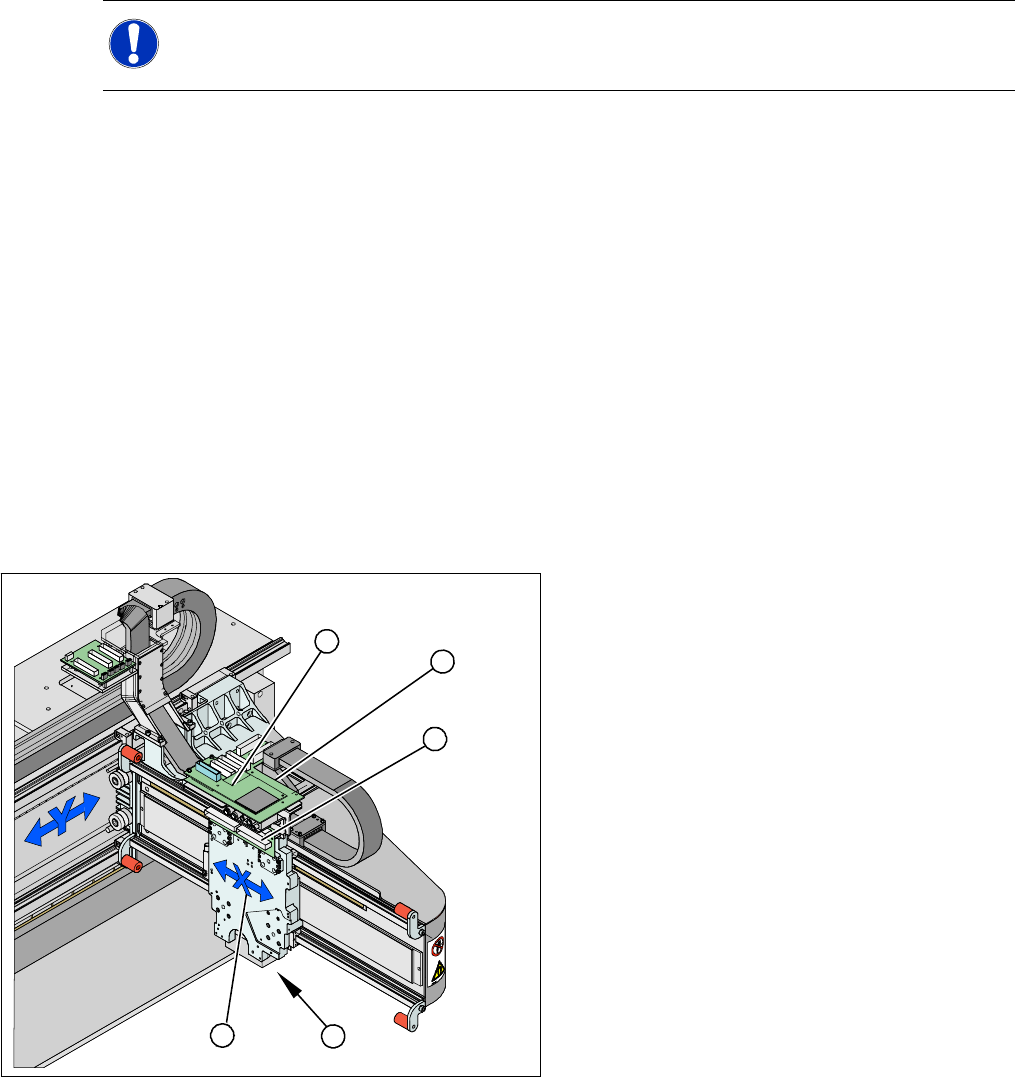
Legend
1. X drive (primary) with head mount
2. X mount with trailing cable
3. Head adapter board
4. Mount with PCB camera
5. Head Board
X Dismantle the placement head.
X Remove the head adapter board (3). The X
mount fixtures (2) are now accessible.
X Unplug the following cables from the head
board (5) and remove them from the X mount
(2):
X motor cable
X axis scanner head
Temperature sensor
5
5
1 4
3
2
Service Work
Gantry D3
70 Servicemanual (internal version) SIPLACE D Series
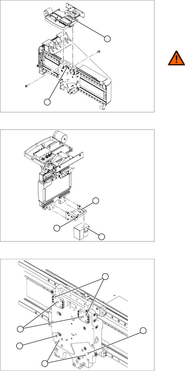
X Unplug the proximity switch cable (2) and pull
it forwards, out of the head mount.
X Undo the 8 screws (4 x at front/ 4x at back)
fastening the X mount (1) and pull these up
and out, together with the trailing cable.
X Fasten the X mount at a suitable point.
DANGER:
Make sure that the flat ribbon cable and
the pneumatic hoses are not rubbed
against any parts or folded. Look out for
sharp edges.
2
1
X Undo the 4 screws fastening the PCB camera
mount (1). Remove the complete unit,
including PCB camera (3) and damping
bracket (2).
X Fix the mount (1) to a suitable point on the
machine base. Take care not to damage the
camera.
1
3
2
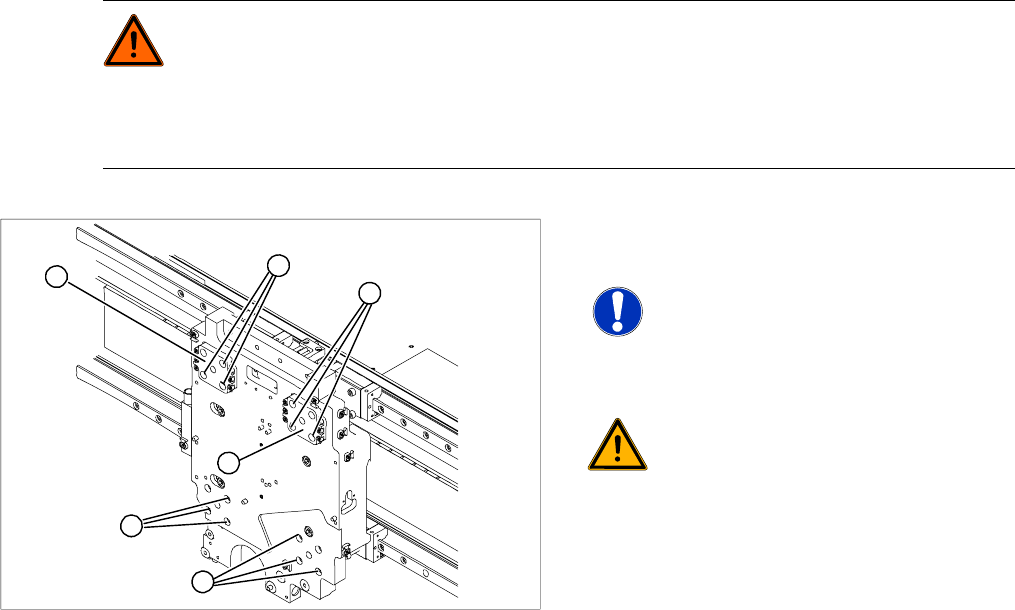
Legend
1. Insert 4 x dismantling screws
2. 4 x lock screws M4x60
X On each of the 4 sides, insert 1 dismantling
screw (1) and tighten as far as the stopper.
X Remove one fastening screw (2) from each of
the 4 sides.
X Replace this fastening screw with a M4x60
lock screw in each case. This prevents the
motor from falling down when pressure is
applied to it.
1
2
2
1
2
Service Work
D3 Gantry
Servicemanual (internal version) SIPLACE D Series
71
DANGER: Risk of fatal injuries through trapped limbs.
Place a piece of foam between the X drive and the magnetic strip for safety purposes.
For additional safety, keep the 4 dismantling screws in place until the X drive has been removed
from the machine.
X Once the X drive is out of the vicinity of the strong magnetic field, it can be removed from the
machine. Loosen the 4 lock screws to remove it.
X Now loosen the 12 remaining fastening screws
(1).
NOTE: Note the screw lengths!
Make a note of the different screw
lengths. These will need to be correctly
replaced later. Mark the positions of the
individual screws.
WARNING:
Do not undo or loosen the screws on
the Z axis compensation (2), which
have been secured with locking
varnish.
X Screw in the dismantling screws in
turn, so that the X drive is evenly
pushed away from the magnetic field
of the magnetic strip. The X drive is
now held by the 4 lock screws.
1
1
1
2
2
M4 x 8
M4 x 18
M4 x 14
1