SIPLACE D系列Servicemanual.pdf - 第84页
Service Wo rk Gantry D4 84 Servicemanual (internal ve rsion) SIPLACE D Series 4-23: Replacing the linear motor - primar y part (2) Legend X Loosen the nine M5 x 20 hexagon socket-h ead screws (3) and remove the primary p…
Service Work
D4 Gantry
Servicemanual (internal version) SIPLACE D Series
83
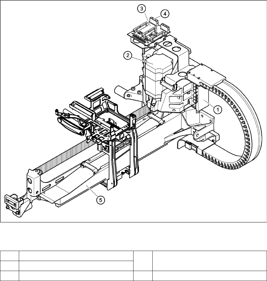
4-22: Replacing the linear motor - primary part (1)
Legend
(1) Linear motor - primary part (4) Socket X4 for the connecting cable of the
primary part
(1) X-axis motor unit
(5) X/Y distributor (5) Gantry
Service Work
Gantry D4
84 Servicemanual (internal version) SIPLACE D Series
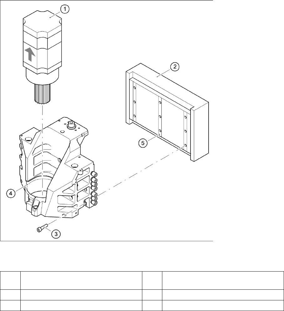
4-23: Replacing the linear motor - primary part (2)
Legend
X Loosen the nine M5 x 20 hexagon socket-head screws (3) and remove the primary part (2).
X Make sure that the lock rails will not drop.
(1) X-axis motor unit (4) Motor bracket with press-fit connection
(pneumatic system)
(1) Linear motor - primary part (5) Lockrail
(5) 9 x M5x20 hexagon socket-head screws
Service Work
D4 Gantry
Servicemanual (internal version) SIPLACE D Series
85
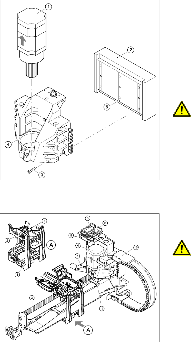
Installing the primary part of the linear motor
Settings
4-24: Replacing the linear motor - primary part
X Fit scotch tape to the lower edge of the primary
part of the linear motor, so that the lockrails (5)
do not fall out during assembly.
X Push in the primary part from the side.
X Fasten the primary part (2) with the nine M5 x
20 hexagon socket-head screws (3) to the
motor bracket (4).
X Make sure that the primary part is aligned in
parallel to the permanent magnet.
X Fit the X-axis motor unit as described in
Section.
X Fix all the cables with cable ties.
CAUTION:
X Make sure that the cables are firmly
seated. Otherwise, the high
acceleration forces may cause the
cable to slip out of position and shear
through.
X Fit the permanent magnets (4 or 16 M6 x 12
hexagon socket-head screws).
X Fit the black cover strips on the crossbeam
above the gantry concerned (3 M6 x 8
hexagon socket-head screws).
4-25: Replacing the X-axis motor unit
X Use the belt tension measuring device to set
the X-axis toothed belt tension to 53 Hz + 1/-3
Hz.
CAUTION:
X Do not overstretch the toothed belt
when adjusting the belt tension.
X Secure the M4x35 hexagon socket-head
screw (2) with the locknut (8).
X Check the axis dynamics of the drives
removed.