SIPLACE D系列Servicemanual.pdf - 第98页
Service Wo rk Placement Heads Replacing the Twin Head Hoses 98 Servicemanual (internal ve rsion) SIPLACE D Series X Move the Z axis upward s. X Insert the feeler gaug e 0.6 mm (2) next to the stopper (1) . X Tighten the …
Service Work
Replacing the Twin Head Hoses Placement Heads
Servicemanual (internal version) SIPLACE D Series
97
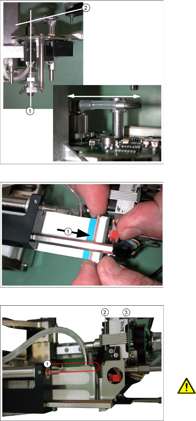
X Move the short hose between the elbow and
the rotary supply.
The rotary supply and the Z axis must be
centered in their guidance (1) .
Press the hose onto the connection or away
from it, until the axis is positioned in the center.
An eccentric position of the Z axis can alter the
balance of forces and lead to placement
errors.
The short hose must also run horizontally (2)
between the elbow and the rotary supply.
X After successfully adjustment, tighten the
screw fastening the elbow.
X Reconnect the long hose at the top.
X Reconnect the flat ribbon cable connector (1).
X Place the flat ribbon baffle on the flat ribbon
cable.
X Place the return unit stopper (2) onto the flat
ribbon baffle.
X Insert the two screws (3) into the stopper.
X Align the flat ribbon baffle to the flat ribbon
cable.
ATTENTION:
The baffle and cable must run parallel
to one another (1)!
Service Work
Placement Heads Replacing the Twin Head Hoses
98 Servicemanual (internal version) SIPLACE D Series
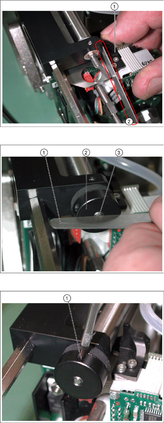
X Move the Z axis upwards.
X Insert the feeler gauge 0.6 mm (2) next to the
stopper (1).
X Tighten the screws fastening the stopper.
X Extract the feeler gauge.
X Screw the bumper (2) in until the underside is
level with the screw (3) (checked with the
feeler gauge (1) on the photo).
X Fix the bumper with the side screw (1).
Service Work
White Balance Process for SIPLACE Digital Vision Camera Placement Heads
Servicemanual (internal version) SIPLACE D Series
99
4.2.3 White Balance Process for SIPLACE Digital Vision Camera
4.2.3.1 General Explanations
In order to compensate for the aging and contamination effects of illumination equipment in SIPLACE
Vision system camera, a white balance process has been planned and developed for this camera
generation.
The illumination factors stored in the camera EPROM have been measured and, where necessary,
adjusted for the individual illumination levels.
A similar balance process existed for the ICOS camera system and was known as the Field Camera
Calibration Service (FCCS) in that case. This abbreviated form was adopted for the SIPLACE Vision
camera system.
4.2.3.2 Cameras and Requirements
The camera white balance process is available from SR/MC 603.01 and is integrated into the SITEST
software. You need a SIEMENS FSE password to access it. The menus for illumination calibration or for
reading out data are available as single steps for the respective individual cameras and as a collective
menu, for all cameras configured at the machine, for complete machine calibration.
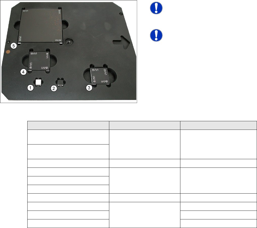
4-30: White balance calibration tools
NOTE:
NEVER touch the white balance
calibration tools!
Avoid contamination of any kind!
NOTE:
This needs to be removed on machines
with the third lane conveyor option.
(from SW 702)
Camera type SST White balance tool Placement head with nozzle
PCB camera SST24
(multicolor illumination option)
7x7 mm white to top (1) ---
PCB camera SST34
(standard illumination)
C&P20 component camera SST23 7x7 mm without fiducials (2) C&P20 with 1135 nozzle
C&P12 SST38 option 24x24 mm with fiducials (3) C&P12 with 920 nozzle
C&P12 SST29 option
C&P12 SST28 standard
C&P6 SST29 standard 30x30 mm with fiducials (4) C&P6 with 820 nozzle
TWIN (P&P) SST33 70x70 mm with fiducials (5) TWIN with 519 nozzle
P&P SST36 P&P with 519 nozzle
TWIN (P&P) SST25 option TWIN (P&P) with 519 nozzle