03217917-01-01E By DEK Technical Reference Manual Vol 1_enPDFA.pdf - 第103页
9 MACHINE CONTROL 9.3 M36 MACHINE CONTROL ENCLOSURE TECHNICAL REFERENCE MANUAL Vol 1 E By DEK 04/2019 103 9.3.3 NextMove Interface Card C A U T I O N A N T I -S T A T I C H A N D L I N G . S T A N D A R D P R E C A U T I…
9 MACHINE CONTROL
9.3 M36 MACHINE CONTROL ENCLOSURE
102 TECHNICAL REFERENCE MANUAL Vol 1 E By DEK 04/2019
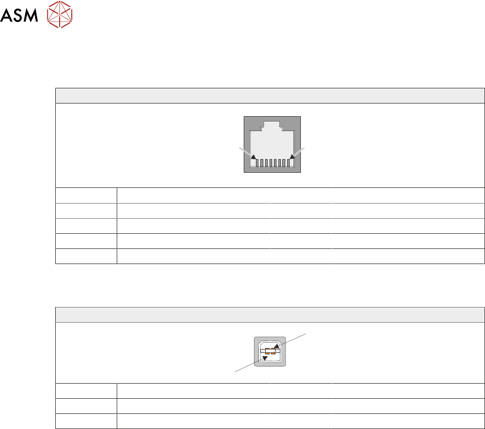
9.3.2.6 CAN Connector
The CAN connector is an RJ45 socket connecting the NextMove card to the various CAN Node
boards and CAN Servo/Stepper motors throughout the machine.
RJ45
1
8
Pin No Signal Pin No Signal
1 CAN+ 5 +24V
2 CAN- 6 N/C
3 N/C 7 N/C
4 0V 8 N/C
9.3.2.7 USB Connector
The USB connector is a Type B socket used to connect the NextMove ES card to the PC..
USB Type B Socket
1
4
Pin No Signal Pin No Signal
1 +5.5V 3 Data+
2 Data- 4 0V
9 MACHINE CONTROL
9.3 M36 MACHINE CONTROL ENCLOSURE
TECHNICAL REFERENCE MANUAL Vol 1 E By DEK 04/2019 103
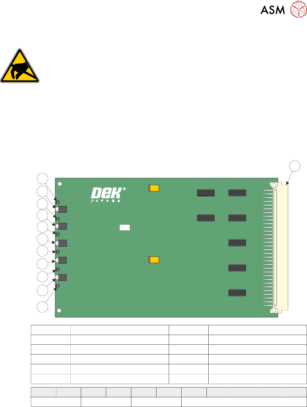
9.3.3 NextMove Interface Card
CAUTION
ANTI-STATIC HANDLING. STANDARD PRECAUTIONS MUST BE ADHERED TO
WHEN HANDLING ELECTRONIC CARDS AND CONFIGURING AND INSERTING
INTO THE ENCLOSURES.
The NextMove Interface card opto-isolates 20 inputs and 7 outputs provided by the NextMove ES
card. Also provided is an Error Out which is used for the Software E Stop power, this is not opto-
isolated.
The card consists of 5 LEDs indicating voltages present and test points for checking and aligning
the voltages required.
The voltages are adjusted in the M37 Power Supply Enclosure, 6.3 "M37 POWER SUPPLY EN-
CLOSURE" [}64].
185020 ISSUE
NEXTMOVE INTERFACE BOARD
1
12
11
10
9
8
7
6
5
4
2
3
1 96 Pin Edge Connector 7 LED 3
2 Test Point 6 (TP6) 8 Test Point 3 (TP3)
3 LED 5 9 LED 2
4 Test Point 5 (TP5) 10 Test Point 2 (TP2)
5 LED 4 11 LED 1
6 Test Point 4 (TP4) 12 Test Point 1 (TP1)
TP 1 LED 1 TP 2 LED 2 TP 3 LED 3 TP 4 LED 4 TP 5 LED 5 TP 6
24V US 24 SW +12V -12V +5.5V DGND
9 MACHINE CONTROL
9.3 M36 MACHINE CONTROL ENCLOSURE
104 TECHNICAL REFERENCE MANUAL Vol 1 E By DEK 04/2019
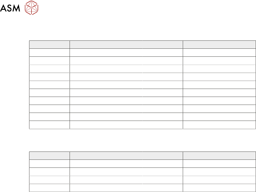
9.3.3.1 Inputs
The following table details the 20 digital inputs for Node 1 Group O:
Input Function Input Function
DIG IN 0 Spare DIG IN 10 Board at Left
DIG IN 1 Spare DIG IN 11 Board at Right
DIG IN 2 Spare DIG IN 12 Jog Left
DIG IN 3 Front Squeegee Home DIG IN 13 Jog Right
DIG IN 4 Rear Squeegee Home DIG IN 14 Power 'ON' Monitor
DIG IN 5 Moving Rail Home DIG IN 15 Cover Interlock
DIG IN 6 Rail Lifted - Left DIG IN 16 Upline Ready
DIG IN 7 Rail Lifted - Right DIG IN 17 Downline Ready
DIG IN 8 Board at Stop DIG IN 18 Board Pass I/P
DIG IN 9 Board Stop Extended DIG IN 19 Spare
9.3.3.2 Outputs
The following table details the 8 digital outputs:
Input Function Input Function
DIG OUT 1 Trigger Image Capture DIG OUT 5 Send Upline
DIG OUT 2 Belt Motors Start-Stop DIG OUT 6 Send Downline
DIG OUT 3 Belt Motors Direction DIG OUT 7 Board Pass O/P
DIG OUT 4 Spare Error Out Software E Stop Power
For all I/O groups select Diagnostics from the Maintenance menu on the machine.