03217917-01-01E By DEK Technical Reference Manual Vol 1_enPDFA.pdf - 第116页
9 MACHINE CONTROL 9.3 M36 MACHINE CONTROL ENCLOSURE 116 TECHNICAL REFERENCE MANUAL Vol 1 E By DEK 04/2019 9.3.5.17 M36SK25 9 Way D Type Socket 1 6 Pin No Signal Pin No Signal 1 CH1 B- 6 N/C 2 N/C 7 CH1 A+ 3 CH1 B+ 8 N/C …
9 MACHINE CONTROL
9.3 M36 MACHINE CONTROL ENCLOSURE
TECHNICAL REFERENCE MANUAL Vol 1 E By DEK 04/2019 115
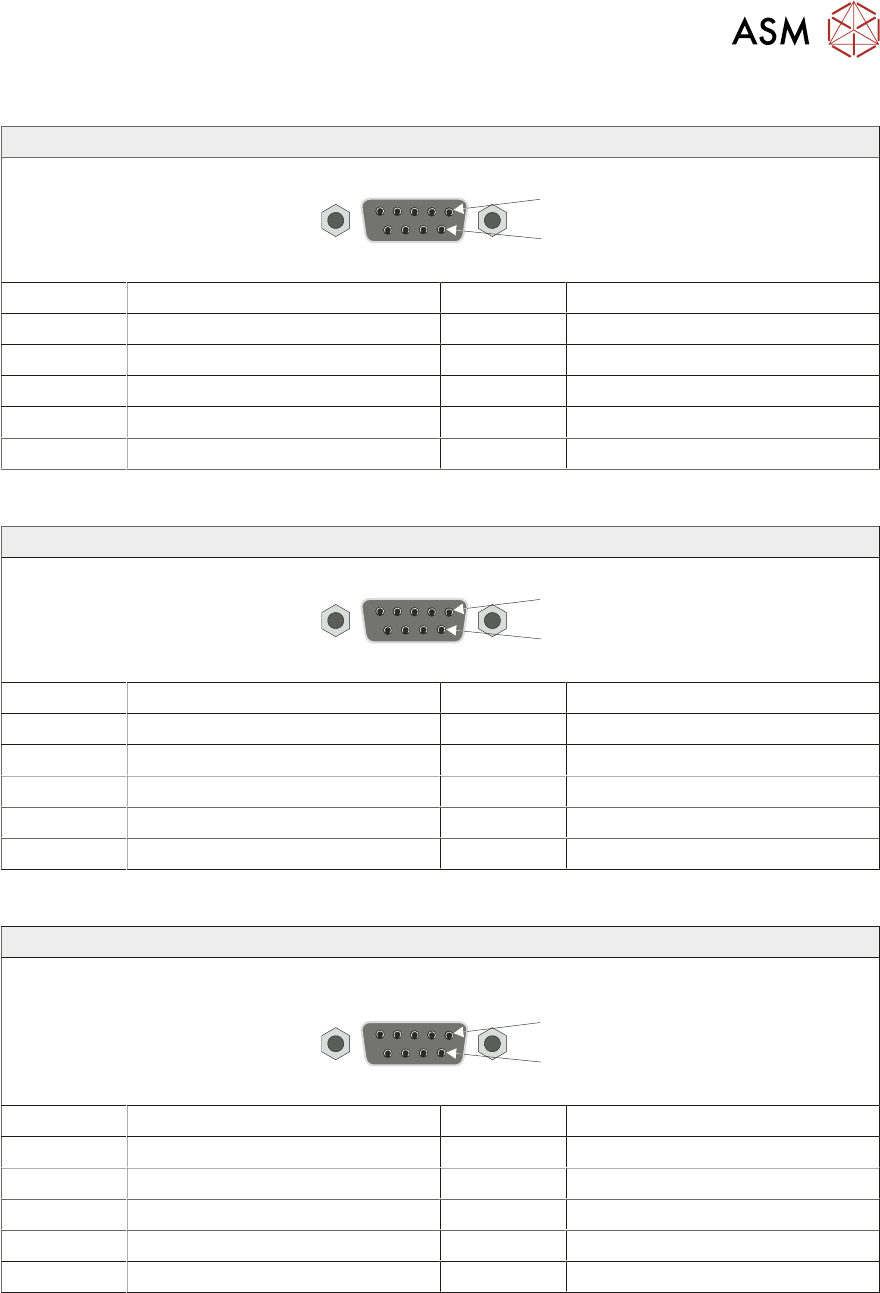
9.3.5.14 M36SK22
9 Way D Type Socket
1
6
Pin No Signal Pin No Signal
1 CH2 B- 6 N/C
2 N/C 7 CH2 A+
3 CH2 B+ 8 N/C
4 N/C 9 N/C
5 CH2 A-
9.3.5.15 M36SK23
9 Way D Type Socket
1
6
Pin No Signal Pin No Signal
1 CH1 B- 6 N/C
2 N/C 7 CH1 A+
3 CH1 B+ 8 N/C
4 N/C 9 N/C
5 CH1 A-
9.3.5.16 M36SK24
9 Way D Type Socket
s
1
6
Pin No Signal Pin No Signal
1 CH2 B- 6 N/C
2 N/C 7 CH2 A+
3 CH2 B+ 8 N/C
4 N/C 9 N/C
5 CH2 A-
9 MACHINE CONTROL
9.3 M36 MACHINE CONTROL ENCLOSURE
116 TECHNICAL REFERENCE MANUAL Vol 1 E By DEK 04/2019
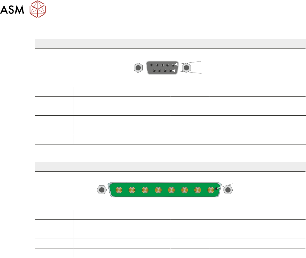
9.3.5.17 M36SK25
9 Way D Type Socket
1
6
Pin No Signal Pin No Signal
1 CH1 B- 6 N/C
2 N/C 7 CH1 A+
3 CH1 B+ 8 N/C
4 N/C 9 N/C
5 CH1 A-
9.3.5.18 M36PL26
8 Way Power D Type Plug
1
Pin No Signal Pin No Signal
1 +12V 5 +24V US
2 0V Return 6 0V Return
3 +24V SW (Belt Motors) 7 +24V SW (Stepper Motors)
4 0V Return 8 0V Return
9 MACHINE CONTROL
9.4 CAN BUS
TECHNICAL REFERENCE MANUAL Vol 1 E By DEK 04/2019 117
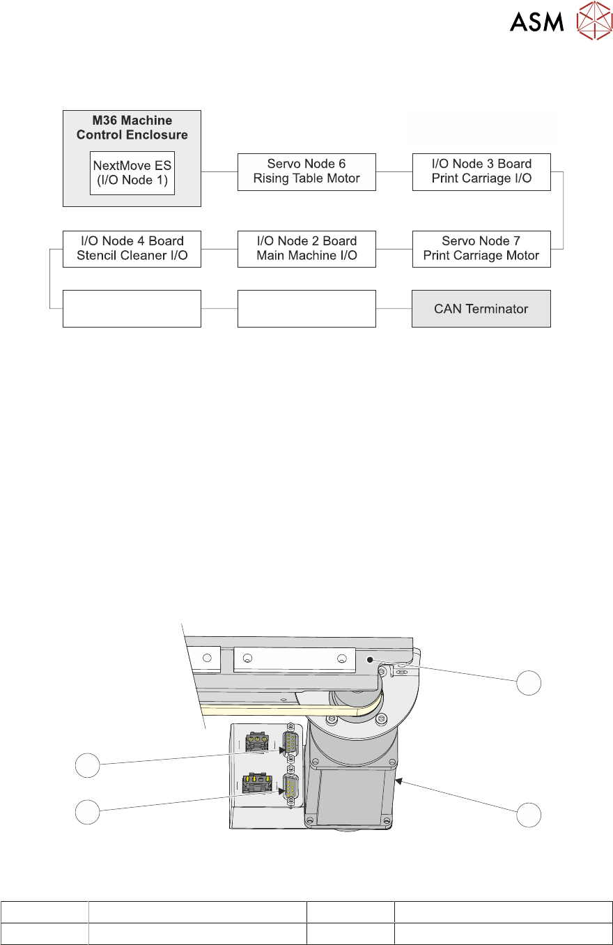
9.4 CAN BUS
Servo Node 9
Camera Y Motor
Servo Node 8
Camera X Motor
CAN Bus
The Controller Area Network (CAN) is a bus system for machine motion control. An encoder/de-
coder for the 500Kbit/s rate CAN serial link is fitted to the NextMove ES card to enable communica-
tion with the CAN Nodes. The CAN is a 2-wire data link designed for transmission of small data
packets for fast update of axis position information.
The CAN Bus connects the NextMove ES card to the Nodes that provide machine motion, switch
functions and sensor feedback. There are two different types of Nodes:
●
I/O Node Boards
●
Stepper Nodes
For the CAN Bus to work correctly, the CAN Bus must be terminated using a CAN Terminator. The
CAN Terminator is fitted to the output connector of the last node in the CAN Bus line and consists
of a 9 pin D type connector with a link resistor fitted inside the connector hood.
1
2
3
4
CAN Terminator Connection
1 Camera Carriage 3 Connector for CAN Bus Input
2 Camera X Motor (Servo Node 8) 4 Connector for CAN Terminator