03217917-01-01E By DEK Technical Reference Manual Vol 1_enPDFA.pdf - 第144页
10 PRINT CARRIAGE MODULE 10.1 OVERVIEW 144 TECHNICAL REFERENCE MANUAL Vol 1 E By DEK 04/2019 1 2 3 4 5 6 7 1 Right Hand Printhead 5 Right Hand Linear Rail 2 Timing Belt 6 Left Hand Printhead 3 Print Carriage 7 Left Hand …
10 PRINT CARRIAGE MODULE
10.1 OVERVIEW
TECHNICAL REFERENCE MANUAL Vol 1 E By DEK 04/2019 143
10
PRINT CARRIAGE MODULE
10.1 OVERVIEW
8
1
2
3
4
5
6
7
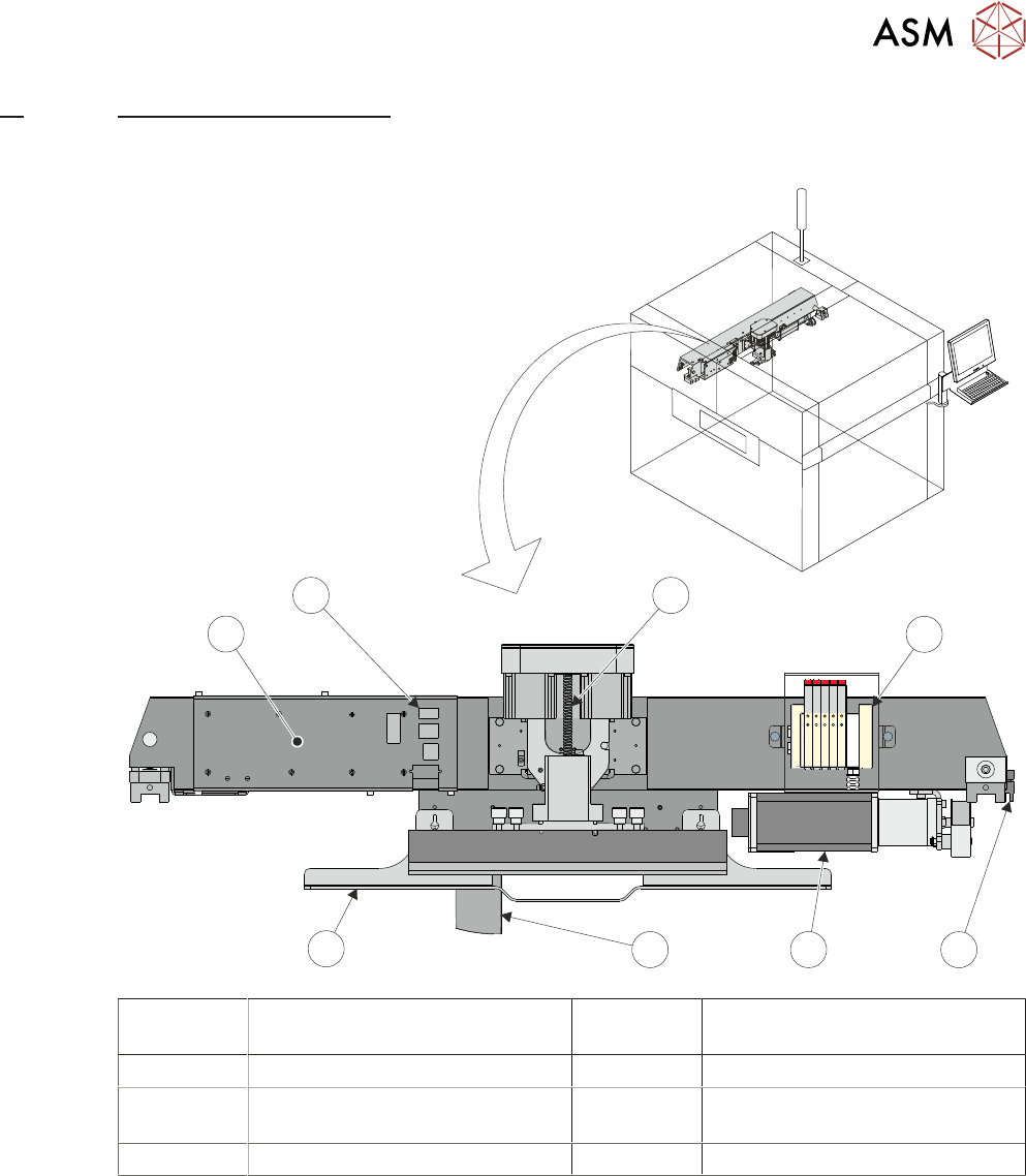
1 Print Carriage Solenoids
(Cover Shown Transparent)
5 Squeegee Drip Tray
2 Print Carriage Home Sensor 6 I/O Node Board 3 (Behind Panel)
3 Print Carriage Servo Motor 7 Printhead Mechanism Connector
Panel
4 Stencil Loader Mechanism 8 Squeegee Printhead Mechanism
10 PRINT CARRIAGE MODULE
10.1 OVERVIEW
144 TECHNICAL REFERENCE MANUAL Vol 1 E By DEK 04/2019
1
2
3
4
5
6
7
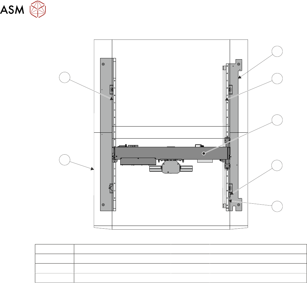
1 Right Hand Printhead 5 Right Hand Linear Rail
2 Timing Belt 6 Left Hand Printhead
3 Print Carriage 7 Left Hand Linear Rail
4 Print Carriage Home Vane
The print carriage enables the following modules to carry out their functions:
●
Printhead Assembly - to transverse across the stencil in the Y direction (print stroke - auto-
matically set from the board width parameter)
●
Screen Change Module - to perform a stencil load or stencil change
All positioning of the print carriage is referenced from the home position and calculated in the
machine software, taking into account:
●
Board Width
●
Front and Rear Print Limits
●
Front Rail Justification
●
Hop-Over Distance
●
Squeegee Pitch
The print carriage only homes during initialisation, which can be from power-up or exiting dia-
gnostics.
I/O Node Board 3, located inside the print carriage extrusion, has an onboard temperature and hu-
midity sensor. For information on I/O Node Board 3 refer to 9.4.4 "I/O Node 3 (Print Carriage I/
O)" [}123].
For information on the print carriage solenoids refer to the Pneumatics Chapter in Volume 2 of this
manual..
10 PRINT CARRIAGE MODULE
10.2 ELECTRICAL SCHEMATIC
TECHNICAL REFERENCE MANUAL Vol 1 E By DEK 04/2019 145
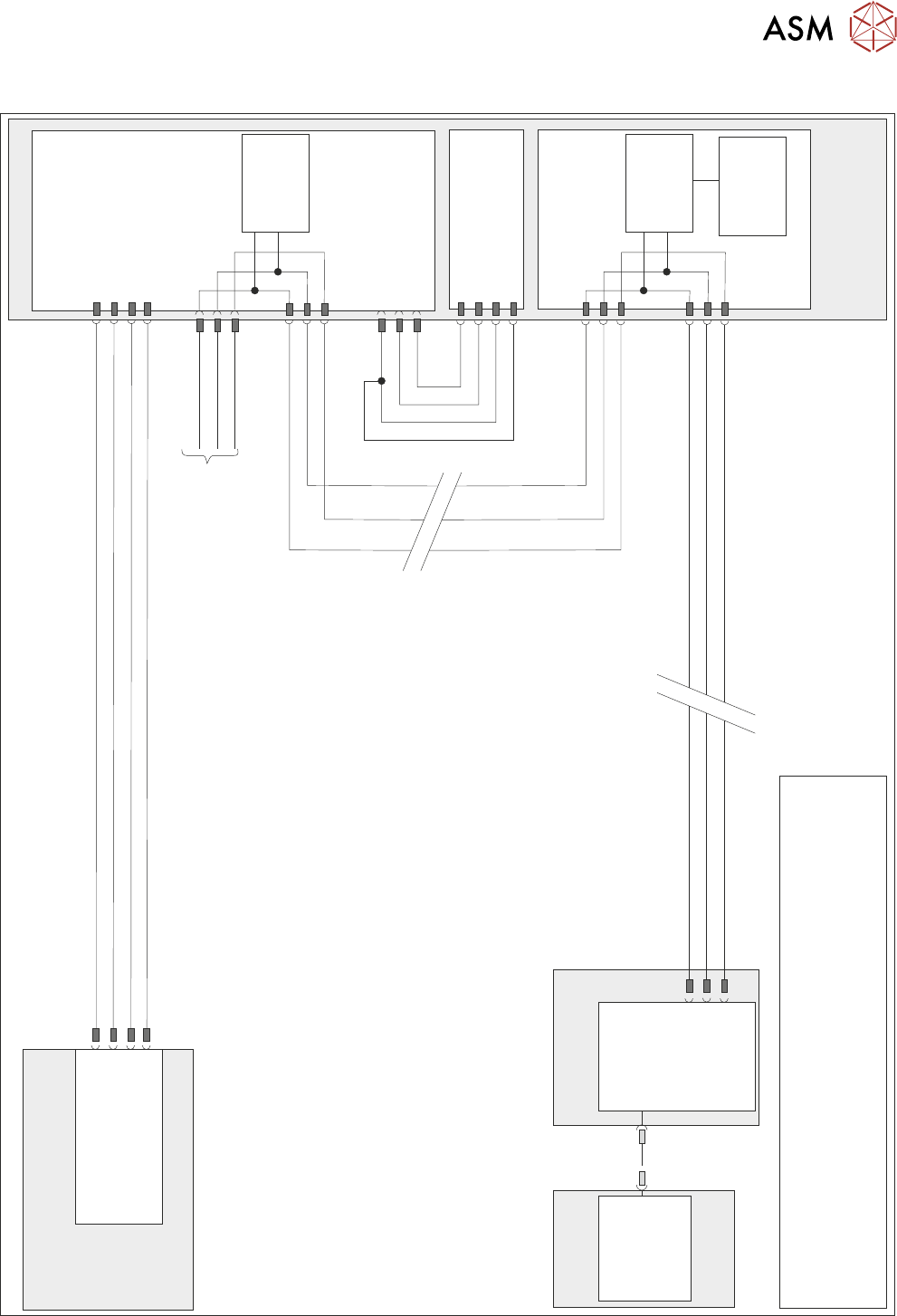
10.2 ELECTRICAL SCHEMATIC
N7SK2
24V US (Motor Logic)
M37 Power Supply Module
Print Carriage
Print Carriage Motor
Node 7
1
2
4
5
Servo DC Supply
0V Return
0V Return
1
2
3
4
Power Distribution
PCB
N7PL1
1
2
3
0V
Signal
24V
9SE03
0V
Signal
24V
(L)
Print Carriage
Home 9SE3
Fork Opto
M37PL17
N7PL4
7
2
3
CAN GND
CAN_L
CAN_H
CAN Out
N7SK3
7
2
3
CAN_L
CAN GND
I/O Node 3
N3SK3
2
3
7
CAN_H
CAN_L
CAN GND
CAN_H
PC
M36 Machine
Control Enclosure
USB
Motherboard
NextMove ES
(I/O Node 1)
1
2
4
CAN_H
CAN_L
CAN GND
M36PL35
N3SK2
2
3
7
CAN_H
CAN_L
CAN GND
CAN
Encoder/
Decoder
CAN
Encoder/
Decoder
Temperature
& Humidity
Sensor
NOTE
The breaks in the CAN Bus chain reflect that additional I/O Nodes
may be fitted, refer to Machine Control chapter for the complete
CAN Bus chain. For print carriage solenoid schematic see Pneumatic
Module chapter.
CAN Bus