03217917-01-01E By DEK Technical Reference Manual Vol 1_enPDFA.pdf - 第146页
10 PRINT CARRIAGE MODULE 10.3 ADJUSTMENTS AND SETTINGS 146 TECHNICAL REFERENCE MANUAL Vol 1 E By DEK 04/2019 10.3 ADJUSTMENTS AND SETTINGS 10.3.1 Home Sensor Adjustment W ARNING BOARD CLAMPS. EXTREME CARE MUST BE EXERCIS…
10 PRINT CARRIAGE MODULE
10.2 ELECTRICAL SCHEMATIC
TECHNICAL REFERENCE MANUAL Vol 1 E By DEK 04/2019 145
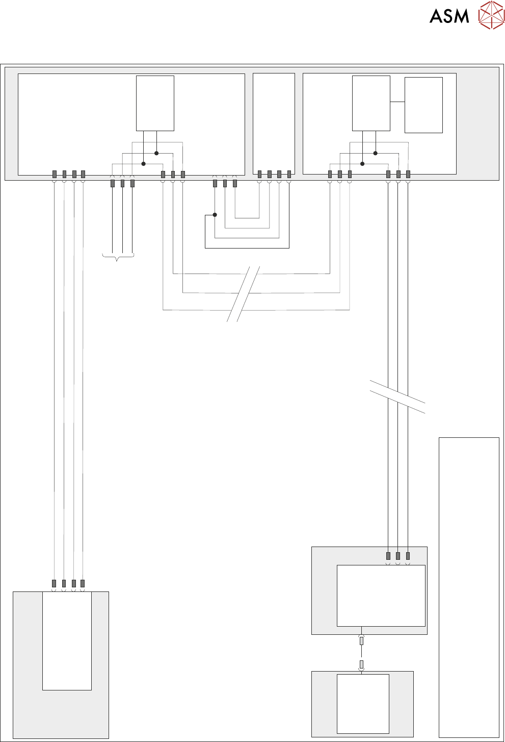
10.2 ELECTRICAL SCHEMATIC
N7SK2
24V US (Motor Logic)
M37 Power Supply Module
Print Carriage
Print Carriage Motor
Node 7
1
2
4
5
Servo DC Supply
0V Return
0V Return
1
2
3
4
Power Distribution
PCB
N7PL1
1
2
3
0V
Signal
24V
9SE03
0V
Signal
24V
(L)
Print Carriage
Home 9SE3
Fork Opto
M37PL17
N7PL4
7
2
3
CAN GND
CAN_L
CAN_H
CAN Out
N7SK3
7
2
3
CAN_L
CAN GND
I/O Node 3
N3SK3
2
3
7
CAN_H
CAN_L
CAN GND
CAN_H
PC
M36 Machine
Control Enclosure
USB
Motherboard
NextMove ES
(I/O Node 1)
1
2
4
CAN_H
CAN_L
CAN GND
M36PL35
N3SK2
2
3
7
CAN_H
CAN_L
CAN GND
CAN
Encoder/
Decoder
CAN
Encoder/
Decoder
Temperature
& Humidity
Sensor
NOTE
The breaks in the CAN Bus chain reflect that additional I/O Nodes
may be fitted, refer to Machine Control chapter for the complete
CAN Bus chain. For print carriage solenoid schematic see Pneumatic
Module chapter.
CAN Bus
10 PRINT CARRIAGE MODULE
10.3 ADJUSTMENTS AND SETTINGS
146 TECHNICAL REFERENCE MANUAL Vol 1 E By DEK 04/2019
10.3 ADJUSTMENTS AND SETTINGS
10.3.1 Home Sensor Adjustment
WARNING
BOARD CLAMPS. EXTREME CARE MUST BE EXERCISED WHEN WORKING IN
THE TOOLING AREA OF THE MACHINE TO AVOID INJURY. THE FOILS ON THE
FRONT AND REAR BOARD CLAMPS ARE VERY SHARP.
► Select Unload Screen.
► Open the printhead cover.
► Remove the stencil from the machine.
► Close the printhead cover.
► Press the System button.
► Select Maintenance.
► Select Diagnostics.
► Use Next or Previous to highlight Print Carriage.
► Select Select Module.
► Ensure that Home Print Carriage is highlighted.
► Select Run Diagnost.
► Use Next or Previous to highlight Drive Carriage To Rear Position.
► Select Run Diagnost.
► Turn the mains isolator OFF; lockout the isolator switch.
► Open the printhead cover.
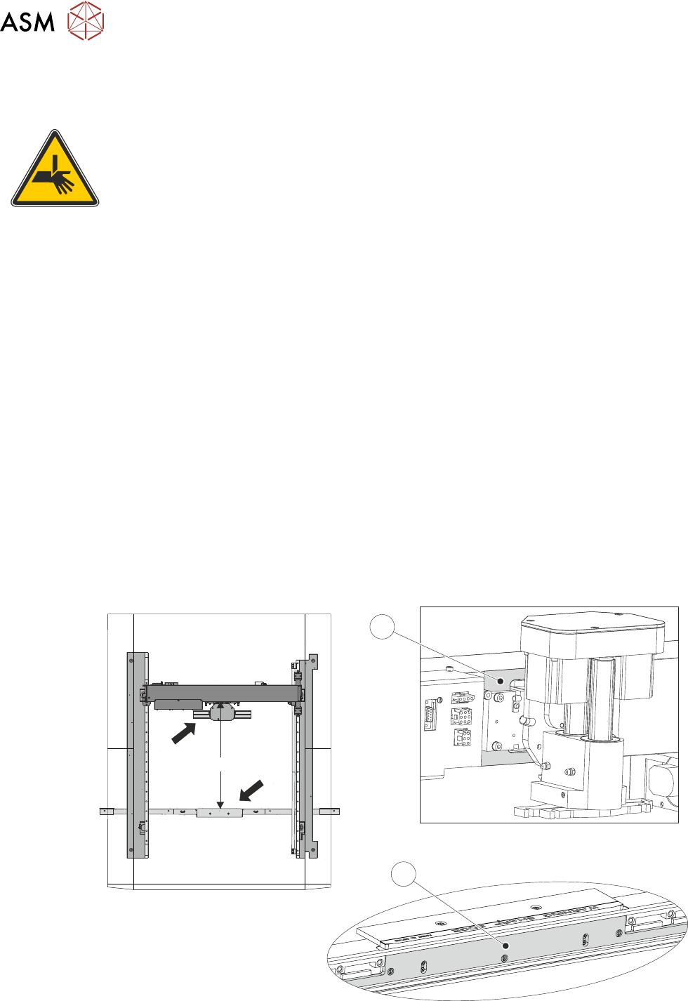
► Measure the horizontal distance between the inside face (2) of the front rail belt support plate
and the print carriage machined face (1), the correct setting being 612.0mm +/- 2.0mm.
View on Arrow A
View on Arrow B
612mm +/- 2.0mm
A
B
1
2
10 PRINT CARRIAGE MODULE
10.3 ADJUSTMENTS AND SETTINGS
TECHNICAL REFERENCE MANUAL Vol 1 E By DEK 04/2019 147
► If the adjustment is correct go to Adjustment Complete - Close Up.
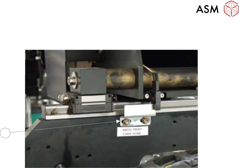
► Gain access to the print carriage home sensor vane (3) on the right hand printhead.
3
► Adjust the position of the home sensor vane (3).
► Close the printhead cover.
► Press the System button.
► Repeat measurement procedure until a measurement of 612.0mm +/- 2.0mm is achieved.
Adjustment Complete - Close Up
► Open the printhead cover.
► Refit the stencil.
► Close the printhead cover.
► Remove the isolator lock; turn the mains isolator switch ON.
► Press the System button.
► Select Exit.
► Select Exit.
► Select Back.