03217917-01-01E By DEK Technical Reference Manual Vol 1_enPDFA.pdf - 第150页
10 PRINT CARRIAGE MODULE 10.5 CALIBRATIONS 150 TECHNICAL REFERENCE MANUAL Vol 1 E By DEK 04/2019 ► Use Next or Previous to highlight Cycle Print Carriage . ► Select Run Diagnost . ► Ensure the print carriage moves smooth…
10 PRINT CARRIAGE MODULE
10.4 REPLACEMENT PROCEDURES
TECHNICAL REFERENCE MANUAL Vol 1 E By DEK 04/2019 149
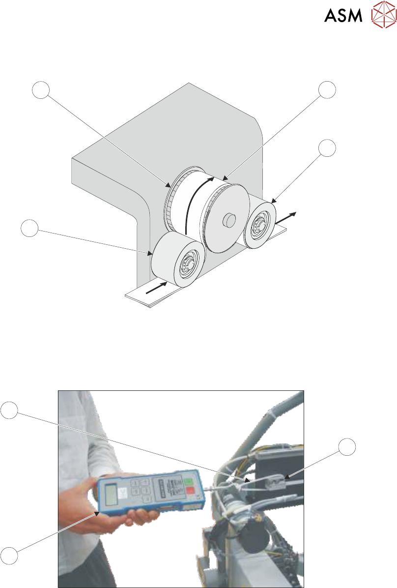
► Thread the timing belt (3) under the front print carriage idle pulley (5), over the print carriage
motor pulley (6) and under the rear print carriage idle pulley (2).
6
3
4
5
► Fasten the belt to the rear belt clamp using the belt securing screws tightened sufficiently to
hold the belt.
► Loosen the rear belt clamp securing screws sufficiently to allow clamp movement.
► Loop a cable tie (9) around the clamp (7).
12.00
7
9
8
► Attach a forcemeter (8) to the cable tie (9) and apply a horizontal force of 12kg.
► Tighten the rear belt clamp securing screws whilst maintaining the tension on the belt.
► Remove the forcemeter (8) and cable tie (9).
► Refit any covers removed for access.
► Remove the isolator lock; turn the mains isolator switch ON.
► Select Maintenance.
► Select Diagnostics.
► Use Next or Previous to highlight Print Carriage.
► Select Select Module.

10 PRINT CARRIAGE MODULE
10.5 CALIBRATIONS
150 TECHNICAL REFERENCE MANUAL Vol 1 E By DEK 04/2019
► Use Next or Previous to highlight Cycle Print Carriage.
► Select Run Diagnost.
► Ensure the print carriage moves smoothly over it’s full range of travel.
► Select Stop.
► Select Exit.
► Select Exit.
► Select Back.
10.5 CALIBRATIONS
10.5.1 Temperature/Humidity Sensor
The temperature/humidity sensor (located on I/O node board 3) is calibrated at manufacture and is
not adjustable.
NOTE
I/O node board 3 is located inside the print carriage extrusion and the temperature and humidity
are measured at this point. Due to heat sources, movement and air flow, it must be expected for
the temperature and humidity to vary throughout the machine.
11 SQUEEGEE MODULE
11.1 OVERVIEW
TECHNICAL REFERENCE MANUAL Vol 1 E By DEK 04/2019 151
11
SQUEEGEE MODULE
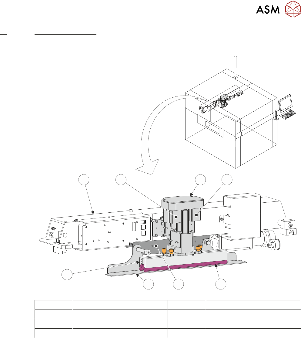
11.1 OVERVIEW
1 2
7 8
6
5
4
3
1 Squeegee Printhead Mechanism 5 Squeegee Drip Tray
2 Rear Squeegee Stepper Motor 6 Rear Squeegee
3 Front Squeegee 7 Print Carriage
4 Squeegee Drip Tray Mechanism 8 Front Squeegee Stepper Motor
The squeegee mechanism is driven backwards and forwards across the stencil by the print car-
riage. The squeegee printhead mechanism incorporates two stepper motors to drive the two
squeegees independently down onto the stencil when a print stroke is required. During the rear-
ward stroke, the front squeegee is in contact with the stencil performing a rear print stroke. During
the forward stroke, the rear squeegee is in contact with the stencil performing a forward print
stroke.
The pressure being applied during the print stroke is measured by a strain gauge bridge (located in
the spring beam assembly of the squeegee mechanism) and if necessary, a correction to the pres-
sure is made by the software.