03217917-01-01E By DEK Technical Reference Manual Vol 1_enPDFA.pdf - 第161页
11 SQUEEGEE MODULE 11.3 REPLACEMENT PROCEDURES TECHNICAL REFERENCE MANUAL Vol 1 E By DEK 04/2019 161 ► Repeat previous two steps for the other belt. ► Hold the new belt in position. Align the teeth of the drive pulley (4…
11 SQUEEGEE MODULE
11.3 REPLACEMENT PROCEDURES
160 TECHNICAL REFERENCE MANUAL Vol 1 E By DEK 04/2019
11.3.1.3 Alternative Drive Belt Replacement (Non-Green Label)
This replacement procedure applies to both front and rear belts. It is advised that drive belts are re-
placed as a pair.
NOTE
The pulley hole centres are fixed. There is no need for pulley belt tension adjustment.
The squeegee drive belts can be replaced without having to remove the printhead mechanism from
the print carriage.
► Select Open Cover Commands.
► Select Carriage To Front.
► Select Back.
► Select Shut Down.
► Select Continue.
► Switch the mains isolator to OFF; lockout the isolator switch.
► Open the printhead cover.
► Remove the squeegees, if fitted.
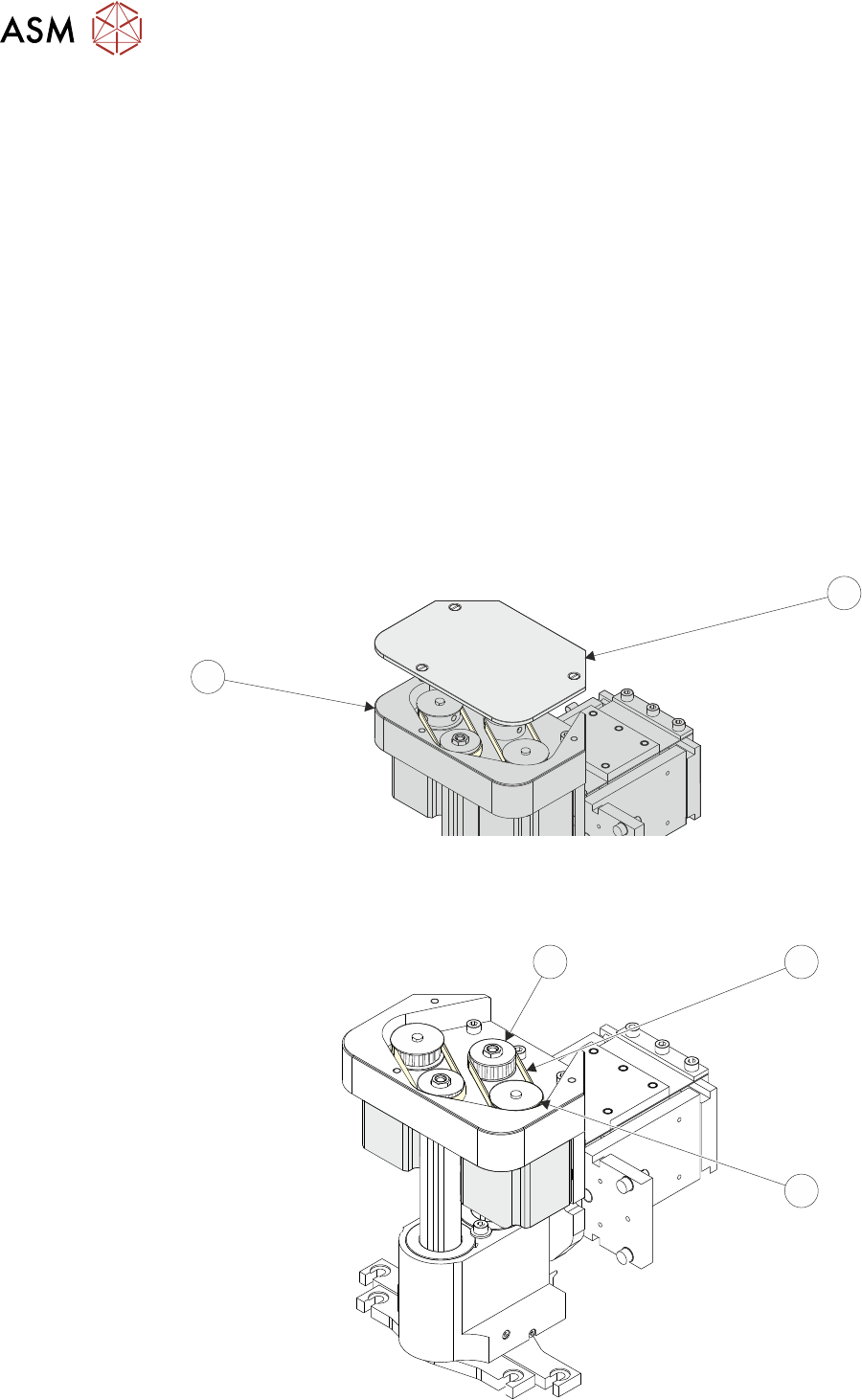
► Remove the drive belt cover plate (1) from the squeegee printhead mechanism (2).
1
2
► Pull the drive belt (3) from its centre and slip it up over the idler pulley (5).
► Slip the belt (3) over the drive pulley (4) and discard it.
3
5
4

11 SQUEEGEE MODULE
11.3 REPLACEMENT PROCEDURES
TECHNICAL REFERENCE MANUAL Vol 1 E By DEK 04/2019 161
► Repeat previous two steps for the other belt.
► Hold the new belt in position. Align the teeth of the drive pulley (4) with the teeth of the belt
and engage the belt on the pulley.
► Whilst maintaining light tension on the belt in the drive pulley (4), to prevent it from slipping off,
rotate the idler pulley (5) to align its teeth with the belts’ teeth.
► Slip the belt down over the idler pulley (5); rotate the idler pulley if necessary to aid fitment
and alignment.
NOTE
Even with power removed the drive pulley (4) does not rotate.
► Repeat previous three steps for the other belt.
► On completion refit the drive belt cover plate (1) and re-connect all leads to the print carriage,
left hand side.
► Refit the squeegees.
► Close the printhead cover.
► Remove the isolator lock; turn the mains isolator ON.
► Press the System button.
11.3.2 Fitting the Squeegees
It is usual to fit two trailing edge squeegees and use the machine in the Print/Print mode.
When fitting a single squeegee (trailing edge or diamond section) to the machine, it must be fitted
to the front squeegee mount only.
The following procedure describes a double trailing edge squeegee configuration fit to the machine
printhead mounting assembly.
► Select Product Setup.
► Select Change Squeegees.
► The print carriage is driven to the front position.
► Open the printhead cover.
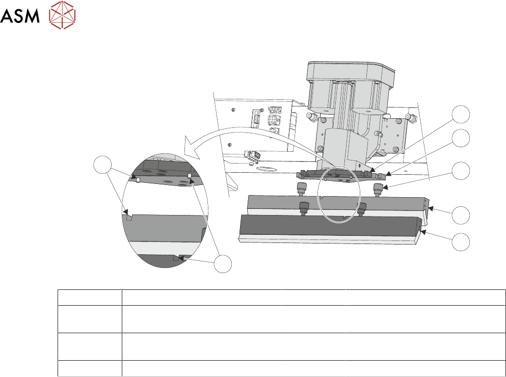
► Fit the rear squeegee to the rear squeegee mount tightening the thumbscrews finger tight.
NOTE
The locking thumbscrews on the rear squeegee are positioned wider apart than those fitted to the
front squeegee and the keyway slot is positioned on the left hand side of the rear squeegee.
► Fit the front squeegee to the front squeegee mount ensuring the thumbscrews are tightened
finger tight.
NOTE
The locking thumbscrews on the front squeegee are positioned closer together than those fitted to
the rear squeegee and the keyway slot is positioned on the right hand side of the front squeegee.
11 SQUEEGEE MODULE
11.3 REPLACEMENT PROCEDURES
162 TECHNICAL REFERENCE MANUAL Vol 1 E By DEK 04/2019
6
6
5
4
3
2
1
1 Front Squeegee Mount 5 Front Squeegee
2 Rear Squeegee Mount 6 Front Squeegee Key and Keyway
Slot
3 Locking Thumbscrew (in 4 posi-
tions)
7 Rear Squeegee Key and Keyway
Slot
4 Rear Squeegee
► Close the printhead cover.
► Press the System button.
► Select Continue.
► Select Back.
► Carry out 11.4.2 "Squeegee Reference Height (Pressure Feedback)" [}165].