03217917-01-01E By DEK Technical Reference Manual Vol 1_enPDFA.pdf - 第168页
11 SQUEEGEE MODULE 11.4 CALIBRATIONS 168 TECHNICAL REFERENCE MANUAL Vol 1 E By DEK 04/2019 11.4.3 Squeegee Reference Height (Non Pressure Feedback) The squeegee reference height is carried out after a squeegee change on …

11 SQUEEGEE MODULE
11.4 CALIBRATIONS
TECHNICAL REFERENCE MANUAL Vol 1 E By DEK 04/2019 167
(Fwd Press Flood) (Rear Press Flood)
(Flood Ref. Height)
(Front Ref. Height) (Rear Ref. Height)
33.1004
31.9668 3951.6971 3947.7037 3935.1178
(steps)
(kg)
Rear Squeegee
4301.000000
4286.000000
4271.000000
4256.000000
4241.000000
4226.000000
4211.000000
4196.000000
4181.000000
4166.000000
4151.000000
4136.000000
4121.000000
4106.000000
4091.000000
4076.000000
4061.000000
4046.000000
4031.000000
4016.000000
22.480215
21.961163
21.503175
21.045188
20.587201
20.068149
19.640694
19.182706
18.724719
18.266732
17.747680
17.289692
17.801172
16.343185
15.885198
15.396678
14.908158
14.480703
13.992184
13.564729
Front Squeegee
(steps)
(kg)
4039.000000
4324.000000
22.388617
21.930630
21.472643
21.045188
20.587201
20.129213
19.640694
19.213239
18.694187
18.266732
17.839277
17.350757
16.892770
16.465315
16.007328
15.579873
15.121886
14.724963
14.236444
13.778456
4309.000000
4294.000000
4279.000000
4264.000000
4249.000000
4234.000000
4219.000000
4204.000000
4189.000000
4174.000000
4159.000000
4144.000000
4129.000000
4114.000000
4099.000000
4084.000000
4069.000000
4054.000000
NOTE
Text shown in italics is not displayed in the Ptest.dat file.

11 SQUEEGEE MODULE
11.4 CALIBRATIONS
168 TECHNICAL REFERENCE MANUAL Vol 1 E By DEK 04/2019
11.4.3 Squeegee Reference Height (Non Pressure Feedback)
The squeegee reference height is carried out after a squeegee change on machines without the
Pressure Hardware option. This procedure must be used if Pressure Hardware is disabled.
Use the following procedure to set the squeegee reference height:
► Select Open Cover Commands.
► Select Carriage To Front.
► Select Unload Screen.
► Open the printhead cover.
► Remove the stencil from the machine.
► Fit the required squeegees to the front and rear squeegee mounts as detailed in 11.3.2 "Fitting
the Squeegees" [}161].
► Close the printhead cover.
► Press the System button.
► Select Back.
► Select Setup Product.
► Select Squeegees.
► Select Calibrate Heights.
► The following machine sequence is carried out:
●
The rails are checked for the presence of a board.
●
The rising table is driven to print height.
●
The board clamps are closed.
●
The print carriage drives the front squeegee over the front rail.
●
The front and rear squeegees are driven down by the stepper motor to dwell height.
Calibrate Front Squeegee
► Select Calibrate Front Squeegee.
► The front squeegee is driven down to the current reference height position.
► Select Jog.
► Open the printhead cover.
► Using a 0.1mm shim placed between the front rail and the front squeegee, check that the
shim moves with a small amount of friction.
► If the gap is correct, go to Calibrate Rear Squeegee.
► For adjustment, select the appropriate Jog Up/Jog Down button on the monitor.
► Using the two button controls simultaneously, jog the squeegee in the chosen direction.
► Recheck the gap.
► Repeat previous three steps until the correct gap is achieved.
Calibrate Rear Squeegee
► Close the printhead cover.
► Press the System button.
► Select Back.
► Select Save.
► Select Calibrate Rear Squeegee.
► The rear squeegee is driven down to the current reference height position.
► Repeat the Calibrate Front Squeegee steps for the rear squeegee.
► Select Back.
► Select Back.
► Select Back.
12 MACHINED C CHASE MODULE
12.1 OVERVIEW
TECHNICAL REFERENCE MANUAL Vol 1 E By DEK 04/2019 169
12
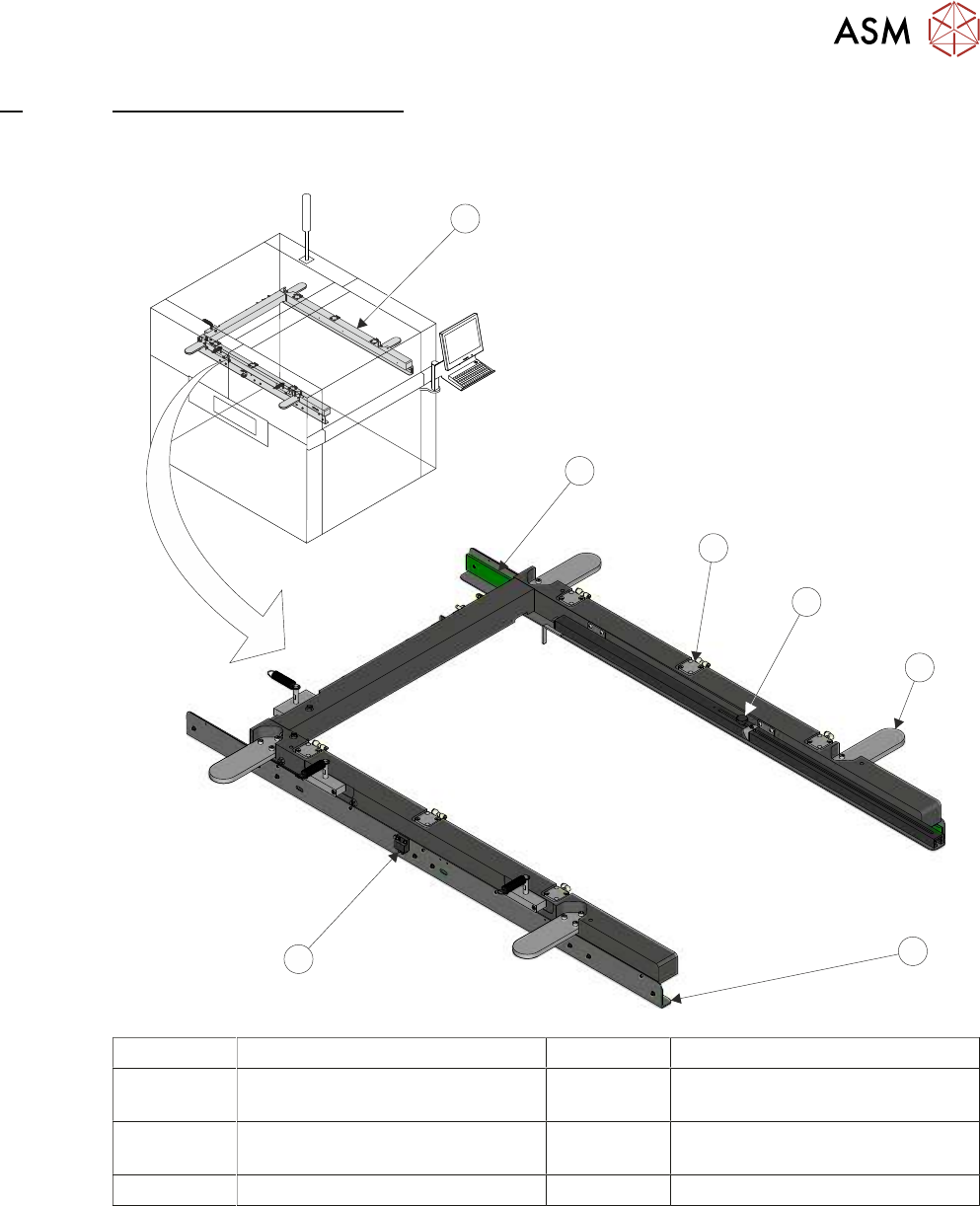
MACHINED C CHASE MODULE
12.1 OVERVIEW
1
2
3
4
5
6
7
1 Machined C Chase 5 Roller Counter Plate (4 positions)
2 Stencil Guide Strip (2 positions) 6 Stencil Support Plate
(in 2 positions)
3 Pneumatic Stencil Clamps
(6 positions)
7 Stencil at Centre Sensor
4 Stencil Depth Adjuster
The machined C chase module is a fixed width system, providing a receptacle for 29 inch square
stencils.
The stencil is loaded from the front of the machine and slid into the machine along the stencil sup-
port plates. The spring loaded right hand stencil guide strip aligns the stencil with the fixed left hand
stencil guide strip.
The stencil is clamped in the chase using pneumatic cylinders that clamp the stencil to the stencil
support plates.
The chase is a floating assembly mounted on a bearing set. The chase is positioned to align the
stencil to the correct printing position. During printing, the chase is pneumatically clamped to the
left and right printhead assemblies to maintain the aligned position, 14 "SCREEN ALIGNMENT
MODULE" [}185] refers.