03217917-01-01E By DEK Technical Reference Manual Vol 1_enPDFA.pdf - 第17页
2 INTRODUCTION 2.3 CONVENTIONS TECHNICAL REFERENCE MANUAL Vol 1 E By DEK 04/2019 17 2.3.3 Safety Notices Safety notices and associated symbols are utilized throughout the complete manual range to high- light to the user …
2 INTRODUCTION
2.3 CONVENTIONS
16 TECHNICAL REFERENCE MANUAL Vol 1 E By DEK 04/2019
2.3 CONVENTIONS
2.3.1 General
The manual follows a logical method of portraying information to the user. This philosophy is con-
sistent across the complete range of manuals.
The following briefly describes the conventions typical of any DEK technical publication.
2.3.2 Page Layout
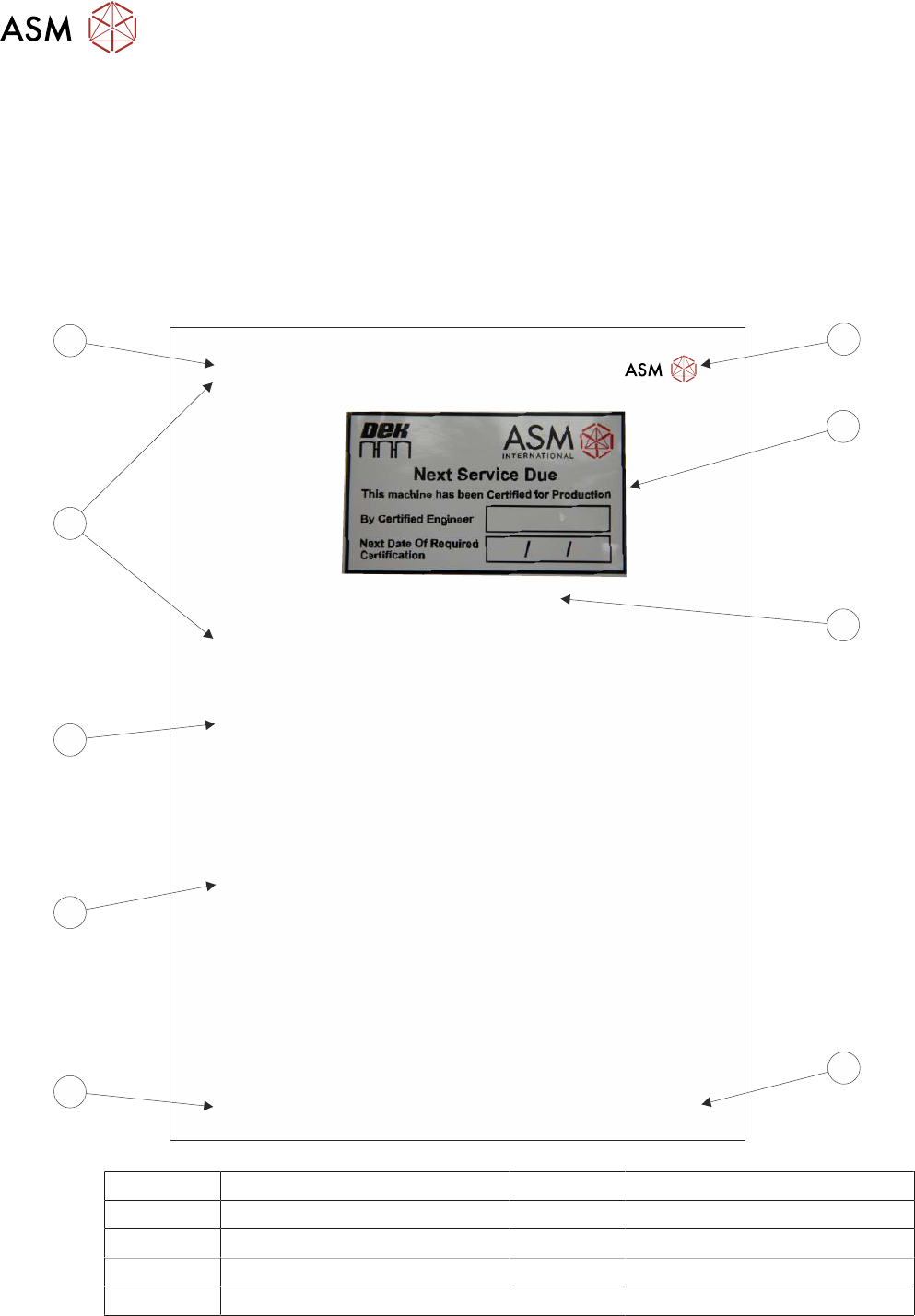
An example of a typical chapter page layout is illustrated below:
1
INTRODUCTION
1.2
MACHINE DESCRIPTION
INSTRUCTION GUIDE E by DEK 07/2017 9
Fig. 3: Next Service Due Label
On subsequent service visits the engineer replaces the label.
1.2 MACHINE DESCRIPTION
The DEK printing machine is a mass imaging device used to apply printable material to substrates
in a controlled manner using a feedback system. Constructed using a torsional rigid machine base
frame, it provides an exceptionally stable print platform, with a high intrinsic resonance frequency.
Coupled with a digital camera system mounted on precision guides delivery longevity and long last-
ing accuracy.
1.2.1 Intended Use
The printer may only be used as a mass imaging device used to apply printable material to PCBs
or substrates. Only ASM AS spares must be used to service the machine.
Using the printer as prescribed also includes the compliance with all instructions on the machine's
GUI and documentation.
For the printer to operate correctly and reliably, it must have been transported, installed, assembled
correctly and must be operated within its specification and environmental envelope.
In the case of incorrect usage, ASM Assembly Systems Singapore Pte Ltd will not assume liability
for any damage which occurs and will not guarantee the correct and proper functioning of machine
or machine components.
1.2.2 Electronic
1.2.2.1 DVD
The following technical information is provided on DVD:
●
Instruction Guide (in all available languages)
●
Operator Manual (in all available languages)
●
Installation Manual
●
Technical Reference Manual
●
Maintenance Manual
●
Electrical Drawings
●
Machine Tutorials
●
Consumable Replenishment Tutorials
1
2
3
4
5
6
7
8
9
1 Company Logo 6 Subject Subtitle
2 Figure 7 Subject Title
3 Figure Number and Title 8 Main Subject Title
4 Page Number 9 Chapter Number and Title
5 Manual Type / Subject / Edition

2 INTRODUCTION
2.3 CONVENTIONS
TECHNICAL REFERENCE MANUAL Vol 1 E By DEK 04/2019 17
2.3.3 Safety Notices
Safety notices and associated symbols are utilized throughout the complete manual range to high-
light to the user the possible risks that may cause injury to personnel (for further information refer to
3 "SAFETY FEATURES" [}21]). An example is shown below:
WARNING
BOARD CLAMPS. EXTREME CARE MUST BE EXERCISED WHEN WORKING IN
THE TOOLING AREA OF THE MACHINE TO AVOID INJURY. THE FOILS ON THE
FRONT AND REAR BOARD CLAMPS ARE VERY SHARP.
2.3.4 Notes
Notes are used extensively throughout the manuals to provide additional information to the user.
Notes are displayed in italic text prefixed by the word in uppercase. An example is shown below:
NOTE
Detailed information regarding print processing in general is highlighted………….
2.3.5 Bold Text
Bold text is used throughout the manuals to identify the following occurrences:
●
An action on the user, (example shown below):
► Select Run Diagnost.
●
A message displayed on the monitor screen, (example shown below):
The following message is displayed: 'Ensure that the correct squeegees are fitted.'
●
A dimension, (example shown below):
► Loosen the securing screw using a 4mm Allen key.
●
A named sub-section of a procedure, (example shown below):
If the calibration jig displays 10kg, go to Calibration Complete.
2.3.6 Cross References
References to other information contained in this two volume manual are displayed in two different
ways, dependent on the volume location of the reference and the reference destination. If the refer-
ence and reference destination are in the same volume of the manual then the cross reference is
displayed as shown below:
●
See 2.3.5 "Bold Text" [}17].
where the initial number is the paragraph number, the following text is the paragraph heading and
the number in square brackets is the page number of the reference destination.
If the reference and reference destination are in different volumes of the manual, the cross refer-
ence is displayed as shown below:
●
See Pneumatics Module chapter in Volume 2 of this manual.
2 INTRODUCTION
2.4 PRINTER OPTIONS
18 TECHNICAL REFERENCE MANUAL Vol 1 E By DEK 04/2019
2.4 PRINTER OPTIONS
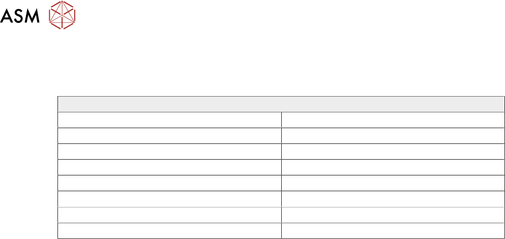
This comprehensive set of manuals cover all possible options available for fitment to this printer.
The table below lists all the available hardware options:
Features
Adjustable Width Stencil Mount (AWSM) Remote Board Stop
Dedicated Tooling Semi-Auto Stencil Loader
Foreign Machine Interface Pod Squeegee Drip Tray
Grid-Lok Tooling Squeegee Pressure Hardware
Heavy Board Rails Stinger
Multi-Interface Unit Temperature and Humidity Sensor
Paste Roll Height Monitor Underscreen Cleaner
Power Monitoring Vacuum Box Tooling