03217917-01-01E By DEK Technical Reference Manual Vol 1_enPDFA.pdf - 第170页
12 MACHINED C CHASE MODULE 12.1 OVERVIEW 170 TECHNICAL REFERENCE MANUAL Vol 1 E By DEK 04/2019 A screen at centre sensor is used to detect the presence of a stencil in the chase. 12.1.1 Screen Loading There is one of two…
12 MACHINED C CHASE MODULE
12.1 OVERVIEW
TECHNICAL REFERENCE MANUAL Vol 1 E By DEK 04/2019 169
12
MACHINED C CHASE MODULE
12.1 OVERVIEW
1
2
3
4
5
6
7
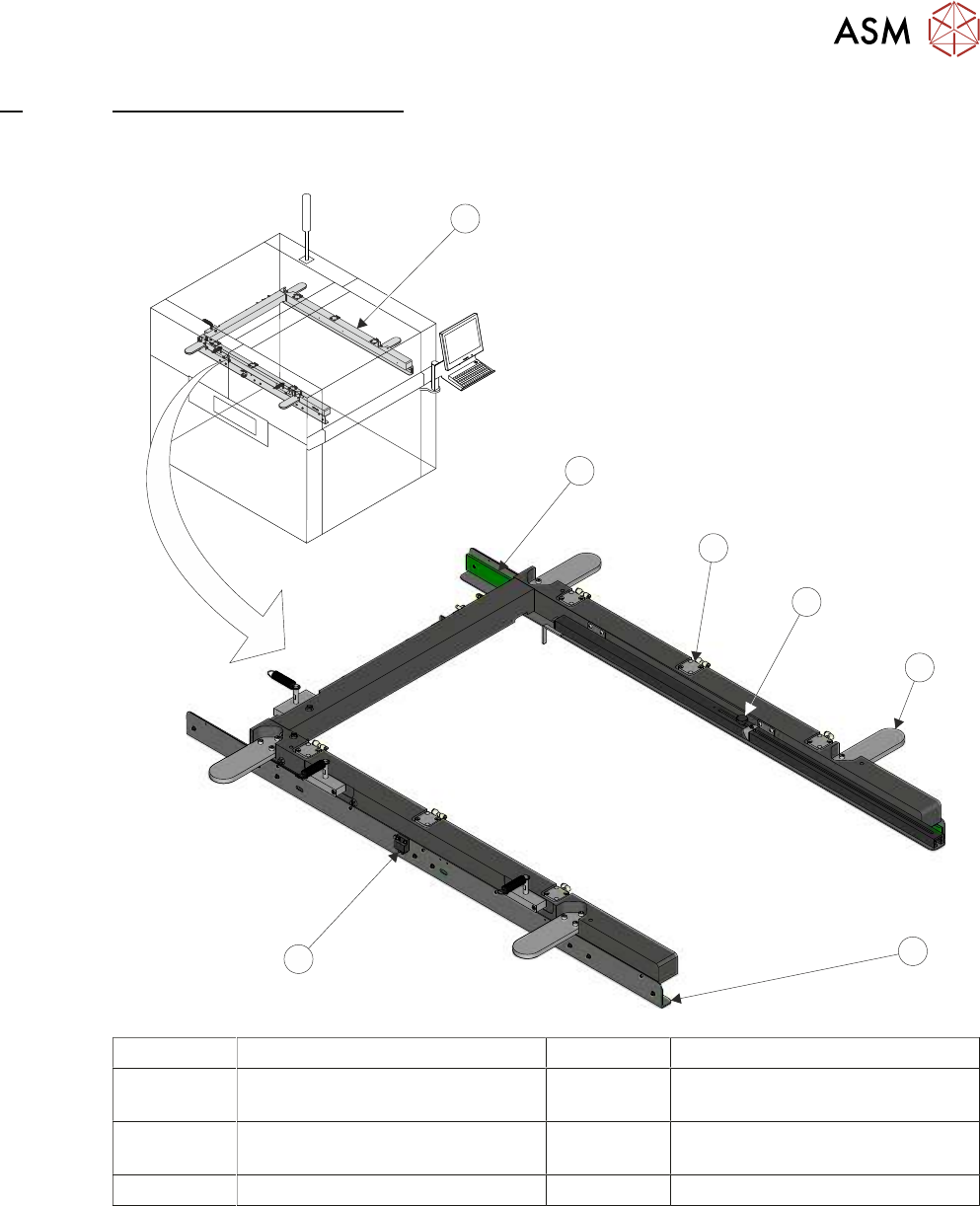
1 Machined C Chase 5 Roller Counter Plate (4 positions)
2 Stencil Guide Strip (2 positions) 6 Stencil Support Plate
(in 2 positions)
3 Pneumatic Stencil Clamps
(6 positions)
7 Stencil at Centre Sensor
4 Stencil Depth Adjuster
The machined C chase module is a fixed width system, providing a receptacle for 29 inch square
stencils.
The stencil is loaded from the front of the machine and slid into the machine along the stencil sup-
port plates. The spring loaded right hand stencil guide strip aligns the stencil with the fixed left hand
stencil guide strip.
The stencil is clamped in the chase using pneumatic cylinders that clamp the stencil to the stencil
support plates.
The chase is a floating assembly mounted on a bearing set. The chase is positioned to align the
stencil to the correct printing position. During printing, the chase is pneumatically clamped to the
left and right printhead assemblies to maintain the aligned position, 14 "SCREEN ALIGNMENT
MODULE" [}185] refers.
12 MACHINED C CHASE MODULE
12.1 OVERVIEW
170 TECHNICAL REFERENCE MANUAL Vol 1 E By DEK 04/2019
A screen at centre sensor is used to detect the presence of a stencil in the chase.
12.1.1 Screen Loading
There is one of two methods used for achieving correct position of the stencil within the chase:
●
Screen Depth Adjuster
●
Semi-Auto Screen Loader
NOTE
Only one of the above items would be fitted to the machine at any one time.
12.1.1.1 Screen Depth Adjuster
20”
24”
650
TO
FRONT
OF
IMAGE
REAR
OF
STENCIL
CENTRE
JUSTIFIED
IMAGE
SIZE
2
3
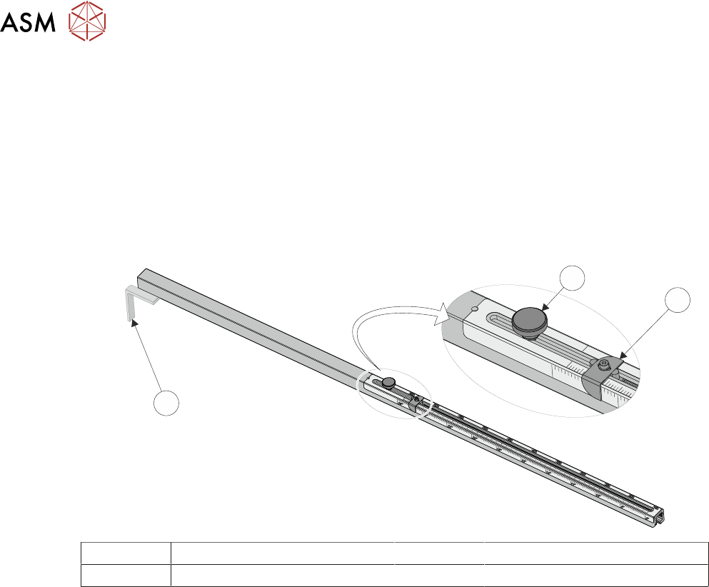
1
1 Measurement Guide 3 Locking Adjustment Knob
2 End Stop
The screen depth adjuster is set by the operator prior to loading the stencil. The stencil is loaded
manually into the chase until it reaches the stop at the end of the screen depth adjuster.
NOTE
For further information on setting the screen depth adjuster, refer to 12.3.1 "Screen Depth Ad-
juster" [}174]in the Adjustments and Settings section of this chapter.
12 MACHINED C CHASE MODULE
12.1 OVERVIEW
TECHNICAL REFERENCE MANUAL Vol 1 E By DEK 04/2019 171
12.1.1.2 Semi-Auto Screen Loader
1 2
3
4
5
6
7
8
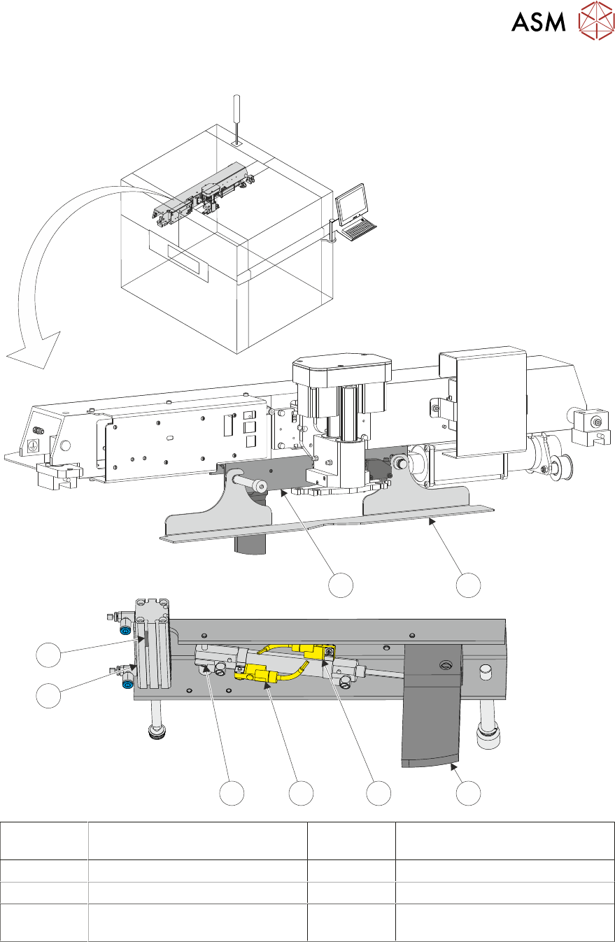
1 Stencil Loader Mechanism 5 Stencil Loader Actuator Retracted
Sensor
2 Squeegee Drip Tray 6 Stencil Loader Actuator
3 Stencil Stop 7 Squeegee Drip Tray Actuator
4 Stencil Loader Actuator Extended
Sensor
8 Drip Tray Retracted Sensor
The semi-auto screen loader mechanism is secured beneath the print carriage, therefore the drive
is provided by the print carriage drive system. The screen loader accurately positions the stencil in
the chase. The mechanism may also incorporate an optional squeegee drip tray.
NOTE
If semi-auto screen loader is installed on the machine, the stencil position sensor is not fitted to the
screen loader mechanism.