03217917-01-01E By DEK Technical Reference Manual Vol 1_enPDFA.pdf - 第174页
12 MACHINED C CHASE MODULE 12.3 ADJUSTMENTS AND SETTINGS 174 TECHNICAL REFERENCE MANUAL Vol 1 E By DEK 04/2019 12.3 ADJUSTMENTS AND SETTINGS 12.3.1 Screen Depth Adjuster The screen depth adjuster has two image scales as …
12 MACHINED C CHASE MODULE
12.2 ELECTRICAL SCHEMATIC
TECHNICAL REFERENCE MANUAL Vol 1 E By DEK 04/2019 173
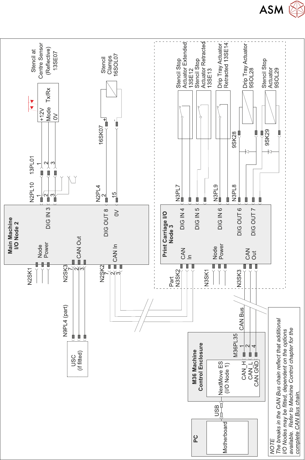
12.2 ELECTRICAL SCHEMATIC
Semi-Auto Stencil Load Option
12 MACHINED C CHASE MODULE
12.3 ADJUSTMENTS AND SETTINGS
174 TECHNICAL REFERENCE MANUAL Vol 1 E By DEK 04/2019
12.3 ADJUSTMENTS AND SETTINGS
12.3.1 Screen Depth Adjuster
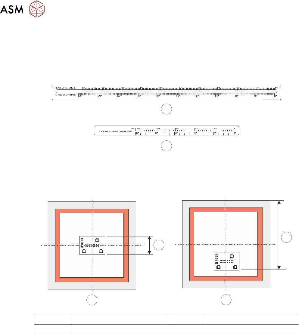
The screen depth adjuster has two image scales as follows:
●
Rear of Stencil to Front of Image (1) - 6 to 26 inches (150 to 650mm)
●
Centre Justified Image Size (2) - 0 to 20 inches (0 to 508mm)
1
2
The rear of stencil to front of image scale is located on the top of the screen depth adjuster.
The centre justified Image size scale is located on the side of the screen depth adjuster.
The following figure shows the measurement for both centre and front justified stencils, when the
stencil is 29 inches square.
1
2
B
A
A Centre Justified Image 1 Board Width
B Front Justified 2 Rear Stencil to Front of Image
NOTE
Rear of stencil to front of image is measured from the rear face of the stencil frame to the front
edge of the image.
The centre justified image scale, marked on the side of the screen depth adjuster, can only be used
for stencils that are 29 inches by 29 inches with a centre justified image. For other stencil sizes with
a centre justified image, the Rear of Stencil to Front of Image scale must be used.
When using the centre justified image scale, the screen depth adjuster is set to
the board width value. The scale has both imperial and metric units as follows:
●
Metric - 0mm to 508mm
●
Imperial - 0 inches to 20 inches
12 MACHINED C CHASE MODULE
12.3 ADJUSTMENTS AND SETTINGS
TECHNICAL REFERENCE MANUAL Vol 1 E By DEK 04/2019 175
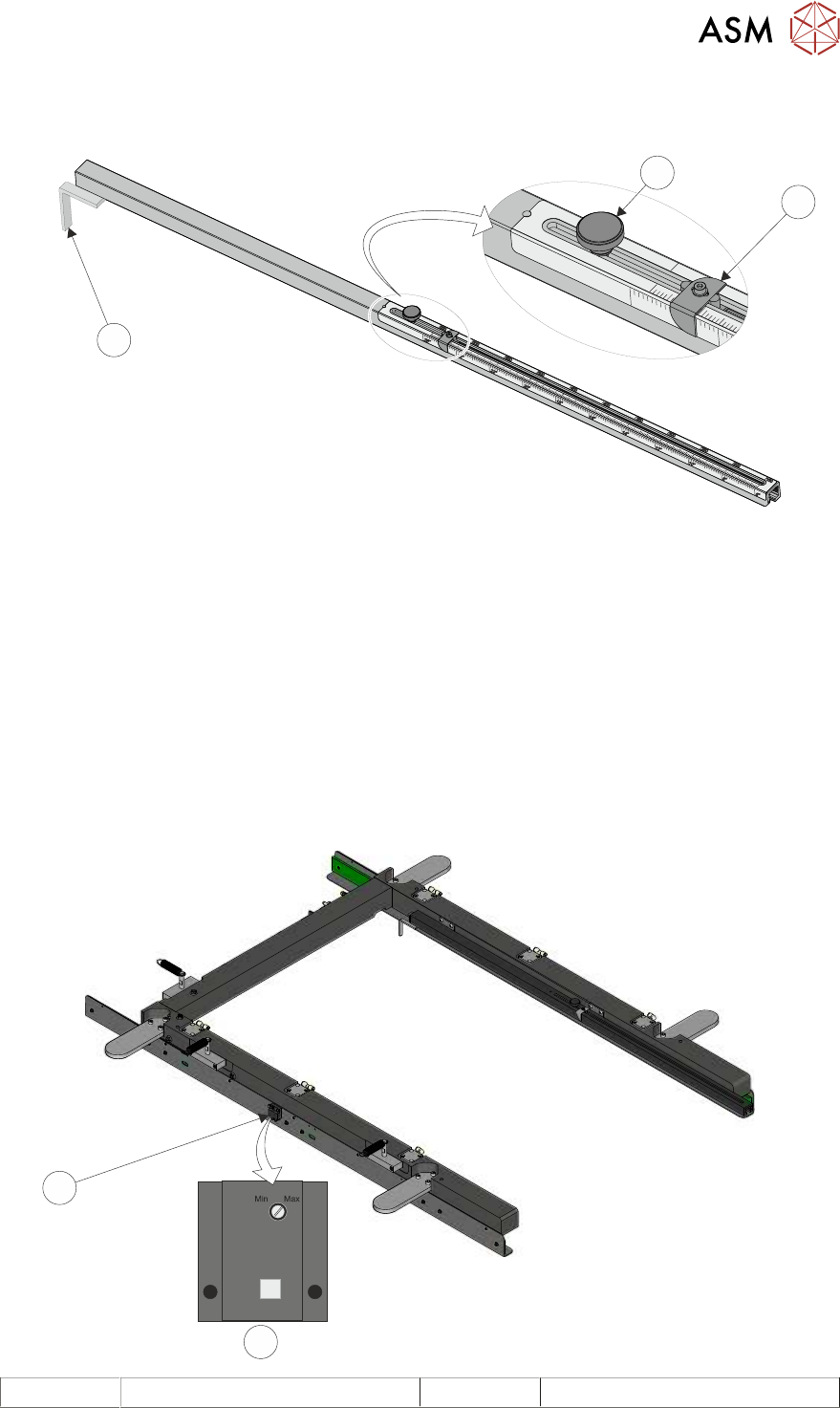
To set the screen depth adjuster, use the following procedure:
► Release the locking adjustment knob (3) by turning it anti-clockwise.
20”
24”
650
TO
FRONT
OF
IMAGE
REAR
OF
STENCIL
CENTRE
JUSTIFIED
IMAGE
SIZE
2
3
1
► Set the measurement guide (1) to either:
The rear of stencil to front of image value, on the top scale, for either centre or front justified sten-
cils.
or
The board width value, on the centre justified image size scale, for centre justified, 29 inch by 29
inch stencils only.
► Turn the locking adjustment knob (3) clockwise to secure the measurement guide.
12.3.2 Screen at Centre Sensor
The Screen at Centre Sensor position is fixed. When fitting a replacement sensor, the sensitivity
adjustment screw should be turned clock-wise to the ‘Max’ position before attaching the sensor to
the sidewall of the C Chase.
1
2
1 Front Face of Sensor 2 Stencil at Centre Sensor