03217917-01-01E By DEK Technical Reference Manual Vol 1_enPDFA.pdf - 第184页
13 ADJUSTABLE WIDTH STENCIL MOUNT 13.3 CALIBRATIONS 184 TECHNICAL REFERENCE MANUAL Vol 1 E By DEK 04/2019

13 ADJUSTABLE WIDTH STENCIL MOUNT
13.3 CALIBRATIONS
TECHNICAL REFERENCE MANUAL Vol 1 E By DEK 04/2019 183
13.3 CALIBRATIONS
13.3.1 Chase to Table Level
Chase to Table Level setting is factory set and no attempt should be made to make adjustment. If
the chase rails have been removed from the printer, a coplanarity procedure must be carried out
before commencing printing. Please contact your local customer support office for more detail.

13 ADJUSTABLE WIDTH STENCIL MOUNT
13.3 CALIBRATIONS
184 TECHNICAL REFERENCE MANUAL Vol 1 E By DEK 04/2019
14 SCREEN ALIGNMENT MODULE
14.1 OVERVIEW
TECHNICAL REFERENCE MANUAL Vol 1 E By DEK 04/2019 185
14
SCREEN ALIGNMENT MODULE
14.1 OVERVIEW
1
2
2
1
9
8
7
6
5
2
4
3
2
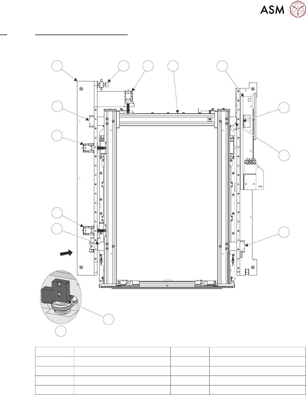
A
A View on Arrow 5 Left Hand Printhead Assembly
1 Chase Clamp (2 positions) 6 Chase Clamp Regulator
2 Roller Counter Plate (4 positions) 7 Y Actuator
3 X Front Actuator 8 AWSM
4 X Rear Actuator 9 Right Hand Printhead Assembly
The screen alignment system is one of the most sensitive and critical components of machine ac-
curacy. The alignment system consists of three stepper motor driven linear actuators in contact
with the chase (adjustable screen mount) which is a free floating mechanism sprung against the
three actuators. The actuators are configured in a three point contact arrangement and are con-
trolled and driven independently to give maximum flexibility in stencil movement.