03217917-01-01E By DEK Technical Reference Manual Vol 1_enPDFA.pdf - 第195页
15 BOARD STOP 15.4 ELECTRICAL SCHEMATIC TECHNICAL REFERENCE MANUAL Vol 1 E By DEK 04/2019 195 15.4 ELECTRICAL SCHEMATIC Motherboard N O T E The breaks in the C A N Bus chain reflect that additional I/O Nodes may be fitte…
15 BOARD STOP
15.3 REMOTE MOUNTED BOARD STOP
194 TECHNICAL REFERENCE MANUAL Vol 1 E By DEK 04/2019
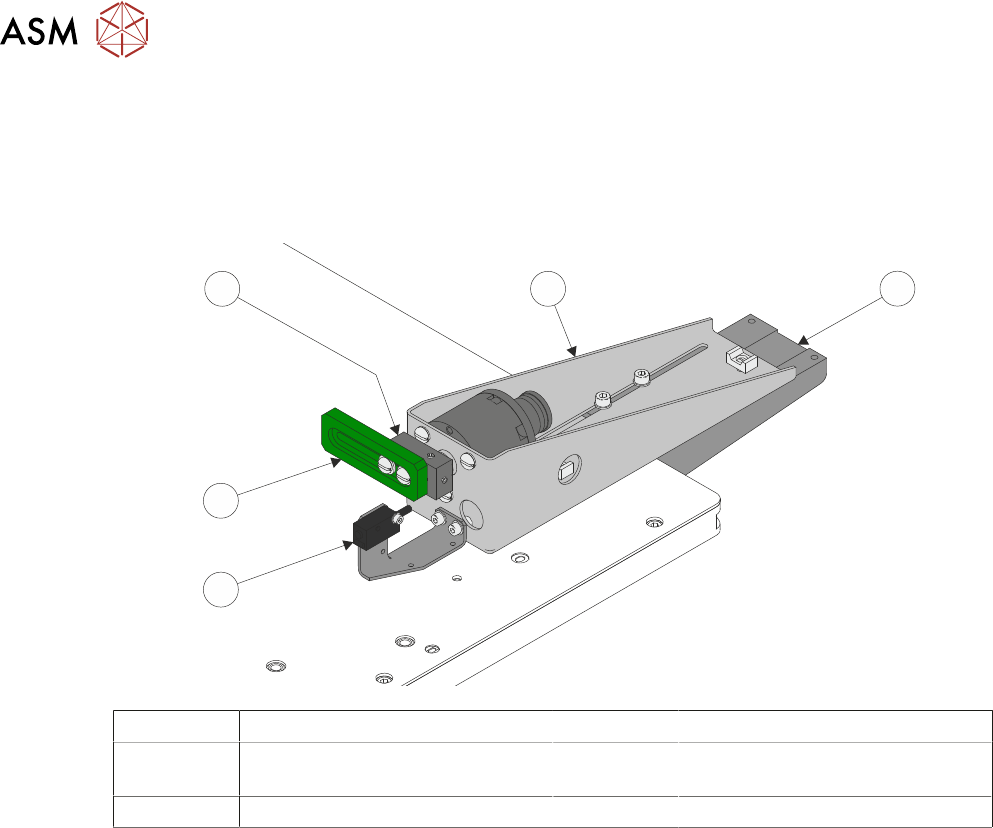
15.3 REMOTE MOUNTED BOARD STOP
The board stop is fitted to the rising table; this assembly is used to aid transportation of heavier
product than can be positioned using the camera board stop assembly.
The remotely mounted board stop can be assembled to stop the product which has been fed into
the printer from either the left hand or right hand side.
1
5
4
3
2
1 Base Clamp 4 Board Stop Rotary Arm
2 Board At Stop Sensor 5 Board Stop Assembly
(shown in RHS Configuration)
3 Board Stop
A product (board) is fed into the printer and passes the Board at Left/Right Sensor. The board con-
tinues on the transport rails; at the same time the camera carriage moves the camera to the loca-
tion where the centre of the board (in X) is aligned to the centre of the white reference dot on the
front rail board clamp (see Note 1). The board, approaching the remote board stop, triggers the
Board at Stop Sensor (see Note 2). The pneumatically driven board stop rotary arm, rotates the
board stop, the control system reads the state of the actuator reed switch and knows that the board
can be stopped in the correct place. The transport rail belts stop, ensuring that the board abuts the
board stop. The board is in the correct position for printing.
NOTES
1. If the board feed is from Right to Left, the board is fed beyond the Board at Stop Sensor be-
fore its direction is reversed. It is then fed back toward stop pin as described previously.
2. If boards have irregularly shaped leading edges, the position of the stop must ensure that the
centre in the X axis is set as described for a plain surfaced board.
3. If the board stop does not work the Board at Stop Sensor may need to be adjusted.
15 BOARD STOP
15.4 ELECTRICAL SCHEMATIC
TECHNICAL REFERENCE MANUAL Vol 1 E By DEK 04/2019 195
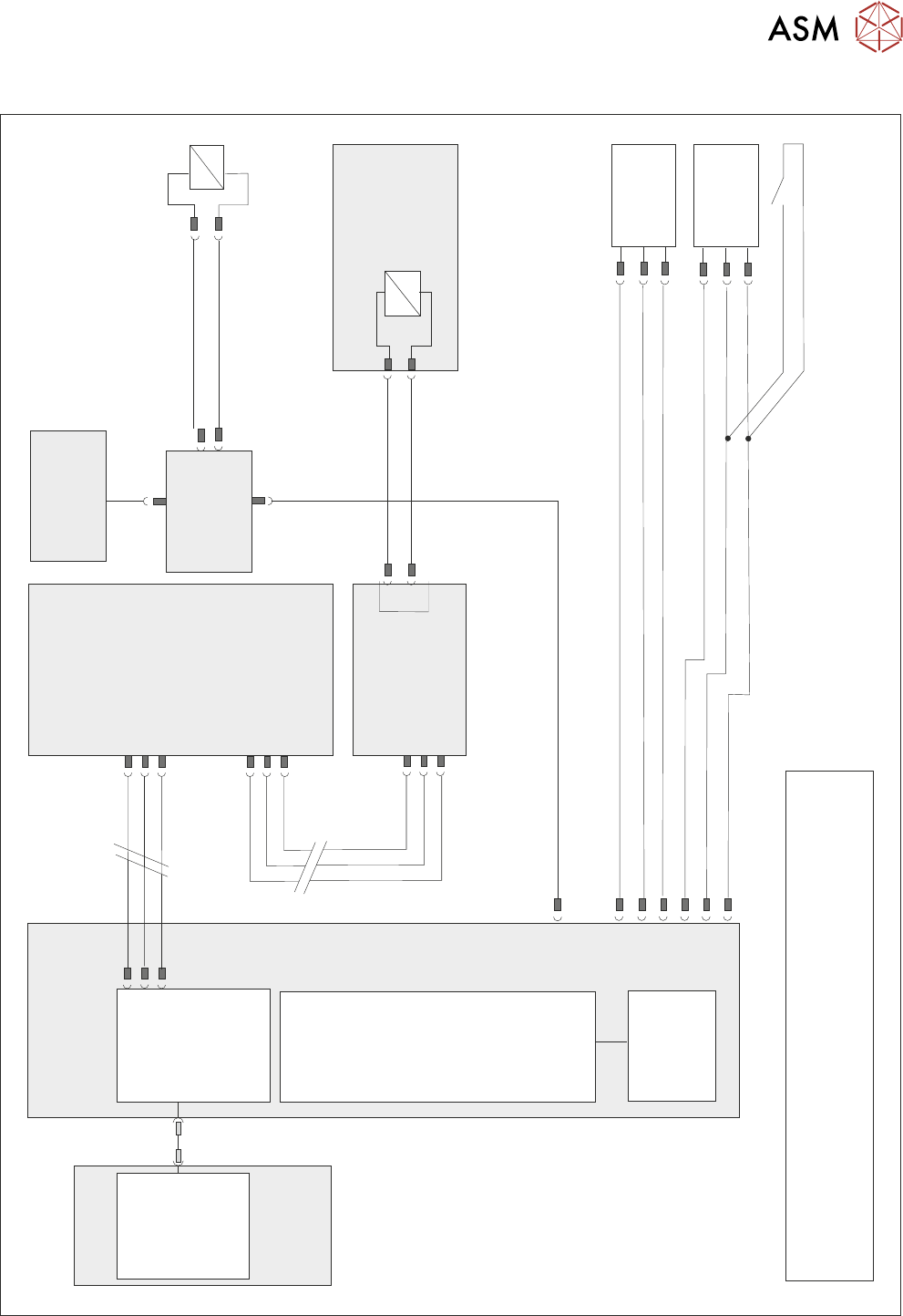
15.4 ELECTRICAL SCHEMATIC
Motherboard
NOTE
The breaks in the CAN Bus chain reflect that additional I/O Nodes
may be fitted, refer to Machine Control chapter for the complete
CAN Bus chain.
DIG OUT 10
N2PL4
Board Stop
Extended
10SE20
Board Stop
Extended
Reed Switch
Board At
Stop
10SE07
M36PL11
0V
0V
+12V
DIG IN 8
DIG IN 9
+12V
NextMove
Interface
NextMove ES
(I/O Node 1)
M36PL35
CAN Bus
Main Machine
I/O Node 2
N2SK2
CAN In
16SK14
16SOL14
Camera Mounted
Board Stop
DIG OUT 10
N2PL4
0V
CAN
Out
N2SK3
10SK24
M36 Machine
Control Enclosure
Main Machine
I/O Node 2
PC
USB
NextMove ES
(I/O Node 1)
1
2
4
CAN_H
CAN_L
CAN GND
M36PL35
CAN Bus N3SK2
7
2
3
CAN In
N2SK2
7
2
3
CAN Out
N3SK3
7
2
3
Print Carriage
I/O Node 3
N2SK4
16SK14
Remote
Board Stop
16SOL14
0V
4
16
Machine Rear Solenoids
CAN Nodes
8&9
15 BOARD STOP
15.5 PNEUMATIC SCHEMATIC
196 TECHNICAL REFERENCE MANUAL Vol 1 E By DEK 04/2019
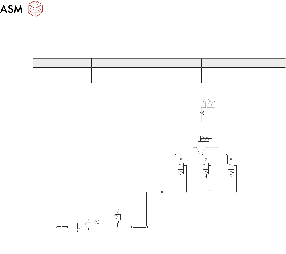
15.5 PNEUMATIC SCHEMATIC
15.5.1 Machine Rear Solenoids
Solenoids are labelled with the solenoid number for identification.
Designation Function Electrical Connection
16SOL14 Camera/Remote Board Stop Digital Out 10 - 16SK14 to
N2SK04
IN
P
Out
Pressure
Sense
Filter/Reg Assy
Mains
Air In
At 4.5 Bar
Minimum
5/2
16SOL08
5/2
16SOL03
5/2
16SOL10
5/2
16SOL14
A
B
AA
B
Machine Rear Solenoids
Camera
Board Stop
Remote Board
Stop