03217917-01-01E By DEK Technical Reference Manual Vol 1_enPDFA.pdf - 第196页
15 BOARD STOP 15.5 PNEUMATIC SCHEMATIC 196 TECHNICAL REFERENCE MANUAL Vol 1 E By DEK 04/2019 15.5 PNEUMATIC SCHEMATIC 15.5.1 Machine Rear Solenoids Solenoids are labelled with the solenoid number for identification. Desi…
15 BOARD STOP
15.4 ELECTRICAL SCHEMATIC
TECHNICAL REFERENCE MANUAL Vol 1 E By DEK 04/2019 195
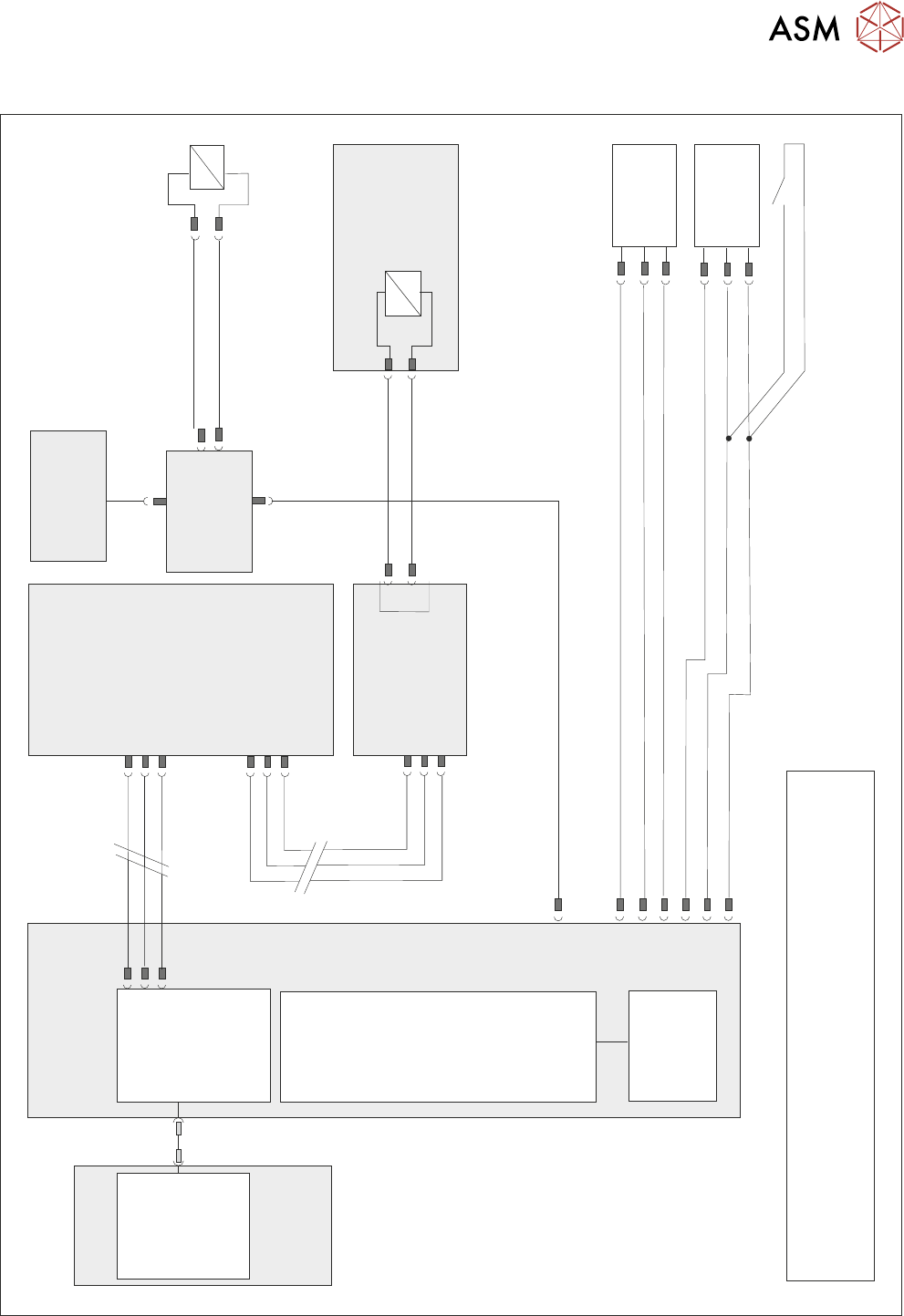
15.4 ELECTRICAL SCHEMATIC
Motherboard
NOTE
The breaks in the CAN Bus chain reflect that additional I/O Nodes
may be fitted, refer to Machine Control chapter for the complete
CAN Bus chain.
DIG OUT 10
N2PL4
Board Stop
Extended
10SE20
Board Stop
Extended
Reed Switch
Board At
Stop
10SE07
M36PL11
0V
0V
+12V
DIG IN 8
DIG IN 9
+12V
NextMove
Interface
NextMove ES
(I/O Node 1)
M36PL35
CAN Bus
Main Machine
I/O Node 2
N2SK2
CAN In
16SK14
16SOL14
Camera Mounted
Board Stop
DIG OUT 10
N2PL4
0V
CAN
Out
N2SK3
10SK24
M36 Machine
Control Enclosure
Main Machine
I/O Node 2
PC
USB
NextMove ES
(I/O Node 1)
1
2
4
CAN_H
CAN_L
CAN GND
M36PL35
CAN Bus N3SK2
7
2
3
CAN In
N2SK2
7
2
3
CAN Out
N3SK3
7
2
3
Print Carriage
I/O Node 3
N2SK4
16SK14
Remote
Board Stop
16SOL14
0V
4
16
Machine Rear Solenoids
CAN Nodes
8&9
15 BOARD STOP
15.5 PNEUMATIC SCHEMATIC
196 TECHNICAL REFERENCE MANUAL Vol 1 E By DEK 04/2019
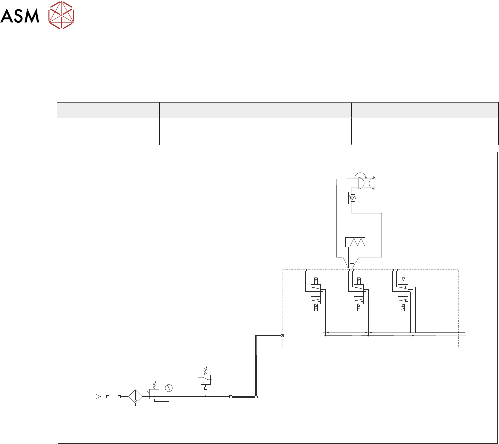
15.5 PNEUMATIC SCHEMATIC
15.5.1 Machine Rear Solenoids
Solenoids are labelled with the solenoid number for identification.
Designation Function Electrical Connection
16SOL14 Camera/Remote Board Stop Digital Out 10 - 16SK14 to
N2SK04
IN
P
Out
Pressure
Sense
Filter/Reg Assy
Mains
Air In
At 4.5 Bar
Minimum
5/2
16SOL08
5/2
16SOL03
5/2
16SOL10
5/2
16SOL14
A
B
AA
B
Machine Rear Solenoids
Camera
Board Stop
Remote Board
Stop
15 BOARD STOP
15.6 ADJUSTMENTS AND SETTINGS
TECHNICAL REFERENCE MANUAL Vol 1 E By DEK 04/2019 197
15.6 ADJUSTMENTS AND SETTINGS
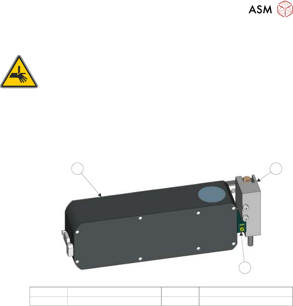
15.6.1 Camera Board at Stop Sensor
WARNING
BOARD CLAMPS. EXTREME CARE MUST BE EXERCISED WHEN WORKING IN
THE TOOLING AREA OF THE MACHINE TO AVOID INJURY. THE FOILS ON THE
FRONT AND REAR BOARD CLAMPS ARE VERY SHARP.
The sensitivity should be adjusted to see a board on the rails at transport height. The distance
between the top of the board and the top of the tooling can change, due to different board thick-
ness, even if the same underside clearance parameter is used. The optimum adjustment is
achieved using the thinnest board, down to a minimum of 0.2mm thick. If the sensor is adjusted
and later a thinner board is used in the machine, it is possible that the decreased distance between
the sensor and the tooling may cause the sensor to be activated while no board is present, due to
tooling being positioned directly below the sensor. If a 0.2mm board is not available, extra care
should be taken to ensure that the sensor is detecting only the top of the board.
3
1
2
1 Camera Mounted Board Stop 3 Camera
2 Board at Stop Sensor
To check and adjust the sensitivity of the board at stop sensor, carry out the following procedure.
Ensure that the rail width is setup for the test board.
► Select Open Cover.
► Select Unload Screen.
► Open the front printhead cover.
► Remove the stencil.
► Close the front printhead cover.
► Press the System button.
► Select Exit.
► Select Maintenance.
► Select Diagnostics.
► Select Confirm.
► Select Print Carriage from the table.
► Select Carriage To Rear.
► Select Back.