03217917-01-01E By DEK Technical Reference Manual Vol 1_enPDFA.pdf - 第203页
15 BOARD STOP 15.6 ADJUSTMENTS AND SETTINGS TECHNICAL REFERENCE MANUAL Vol 1 E By DEK 04/2019 203 15.6.3 Setting the Remote Board Stop W ARNING BOARD CLAMPS. EXTREME CARE MUST BE EXERCISED WHEN WORKING IN THE TOOLING ARE…
15 BOARD STOP
15.6 ADJUSTMENTS AND SETTINGS
202 TECHNICAL REFERENCE MANUAL Vol 1 E By DEK 04/2019
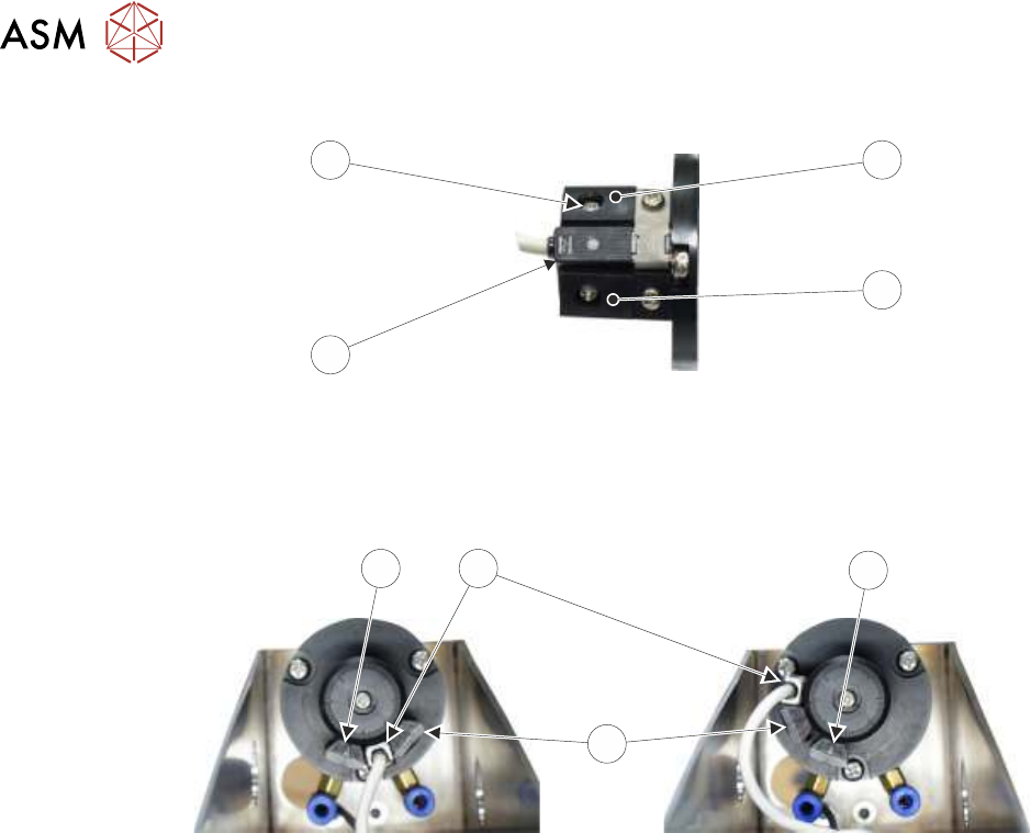
7
6
4
5
► Rotate the reed switch (6) and adjustable stop (4) anti-clockwise until the adjustable stop (4)
abuts the fixed stop (5).
► Tighten the adjustable stop securing screw (7) through the access hole.
LH
RH
5
6
5
4
► Continue with the appropriate one of the following procedures:
●
15.6.5 "Camera to Remote Board Stop - RHS Configuration" [}210]
●
15.6.6 "Remote Board Stop - LHS to RHS Configuration" [}214]

15 BOARD STOP
15.6 ADJUSTMENTS AND SETTINGS
TECHNICAL REFERENCE MANUAL Vol 1 E By DEK 04/2019 203
15.6.3 Setting the Remote Board Stop
WARNING
BOARD CLAMPS. EXTREME CARE MUST BE EXERCISED WHEN WORKING IN
THE TOOLING AREA OF THE MACHINE TO AVOID INJURY. THE FOILS ON THE
FRONT AND REAR BOARD CLAMPS ARE VERY SHARP.
This adjustment sets the position and the height of the remote board stop with respect to the
product board to be printed.
► Select Open Cover Commands.
► Select Unload Screen.
► Open the printhead cover.
► Remove the screen from the machine.
► Mark the centre point, in the X axis, on the front of the product board.
► Select Board Clamps to release the clamps.
► Place the product board on the rails with the board centre point at the Camera Reference Po-
sition (white dot on front rail).
► Select Board Clamps to clamp the board in place.
► Close the printhead cover.
► Press the System button.
► Select Back.
► Select Setup Product.
► Select Tooling and make a note of the value of the Under Clearance parameter.
► Select Back.
► Select Back.
► Select Maintenance.
► Select Diagnostics.
► Use Next or Previous to highlight Rising Table.
► Select Select Module.
► Use Next or Previous to highlight Raise Table To Vision Height.
► Select Run Diagnost. The table is driven to vision height and the board is clamped.
► Use Next or Previous to highlight Drive Table Using Jog Buttons.
► Select Run Diagnost.
► Remove one of the safety covers to gain access to the rail height adjusters.
15 BOARD STOP
15.6 ADJUSTMENTS AND SETTINGS
204 TECHNICAL REFERENCE MANUAL Vol 1 E By DEK 04/2019
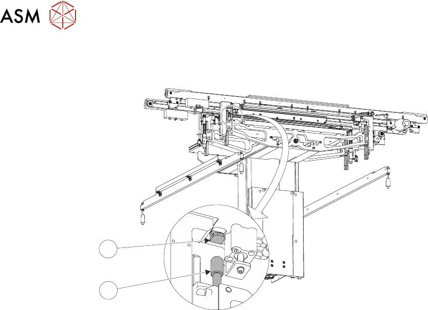
► Drive the table down so that the gap between the top of the rail height adjuster (1) and the
striker plate (2) is the same as the Under Clearance parameter noted previously.
1
2
► Open the front printhead cover.
► Position the remote board stop assembly on the base clamp so that the board stop abuts the
board.
► Tighten the four M5 cap head screws using a 5mm Allen key.
► Close the front printhead cover.
► Press the System button.
► Select Exit.
► Use Next or Previous to highlight Rail System.
► Select Select Module. The board clamps are released.
► Open the front printhead cover.
► Move the board back to the board stop and set the height of the board stop to approximately
2mm above the board.
► Adjust the setting of the board at stop sensor, 15.6.3.1 "Board At Stop Sensor" [}204] refers.
15.6.3.1 Board At Stop Sensor
This adjustment sets the sensitivity of the board at stop sensor.
► Close the front printhead cover.
► Press the System button.
► Select Continue.
► Select Exit.
► Use Next or Previous to highlight Rising Table.
► Select Select Module.
► Use Next or Previous to highlight Raise Table To Transport Height.
► Select Run Diagnost.
► Open the front printhead cover.