03217917-01-01E By DEK Technical Reference Manual Vol 1_enPDFA.pdf - 第21页
3 SAFETY FEATURES 3.1 OVERVIEW TECHNICAL REFERENCE MANUAL Vol 1 E By DEK 04/2019 21 3 SAFETY FEATURES 3.1 OVERVIEW The printer incorporates various safety features that provide a safe operating environment for the operat…
2 INTRODUCTION
2.5 GLOSSARY
20 TECHNICAL REFERENCE MANUAL Vol 1 E By DEK 04/2019
Term Definition
Module Self contained assembly of mechanical and/or electronic construc-
tion.
Nano-ProTek A protective coating that is applied to stencils, which gives better re-
lease characteristics and extends the life of the stencil, benefitting
from fewer cleaning cycles.
Parameter Variable quantity which once set becomes the datum for other
mathematical functions.
Paste Roll Height Monitor A system which measures the paste roll. The user can program the
print cycle to apply more paste exactly when it is needed most.
Print Medium The material used to print/transfer onto a board, wafer or substrate
– Pastes/Adhesives/Enzymes/Inks.
QC Calc External computer program that provides statistical analysis of cer-
tain machine functions.
ROI Region of Interest. An area representing the current 2D inspection
site superimposed on both stencil and board images within the vis-
ion data window.
Schematic Representational diagram of a system.
Screen An emulsion coated mesh of various thicknesses, stretched onto a
frame with an image photographically processed into the emulsion,
through which solder paste or other media can be deposited in a
controlled fashion onto a board or other surface.
SMEMA Surface Mount Equipment Manufacturer Association. A standard
type of FMI protocol.
SMPSU Switched Mode Power Supply Unit, situated in the machine power
supply module. Produces various dc voltages for the machine.
SPC Statistical Process Control. Collection of outputs from the machine
used by QC Calc program.
Squeegee Device, usually rubber or metal used to distribute printable material
across and through the screen during the print cycle.
Stencil A shim, usually metal that has an appropriate image cut through it.
The shim is secured to a metal frame through which solder paste or
such media, can be deposited in a controlled fashion onto a board
or other such surface.
Stinger Adhesive dot deposition system.
Upline A term referring to an item or piece of equipment within a produc-
tion line situated above the DEK machine moving against the direc-
tion of the line towards the beginning of the line.
USB Universal Serial Bus. The USB is a two wire data link designed for
two way communications between the machine PC and the follow-
ing: M36 machine controller; M37 power supply; 4 port USB hub.
USC Under Screen Cleaner. A programmable module for cleaning the
underside of a screen/stencil.
3 SAFETY FEATURES
3.1 OVERVIEW
TECHNICAL REFERENCE MANUAL Vol 1 E By DEK 04/2019 21
3
SAFETY FEATURES
3.1 OVERVIEW
The printer incorporates various safety features that provide a safe operating environment for the
operators/maintainers using:
●
Safety interlocks ensure that potentially hazardous machine operations can only be performed
when the machine is in a safe condition
●
Safety labels to inform the user of areas where danger or residual danger may exist
All safety circuits have been designed to meet the safety requirements as outlined in the machines’
CE Declaration of Conformity. The circuits check for welded contacts before resetting. Additional
safety is achieved by duplication of the power contactors to provide redundancy.
3.1.1 Mains Supply
Where incoming hazardous supply voltages are present, protection is afforded by controlling
access to the enclosures that house the supply. The enclosures require tools to gain access to the
inside and must only be opened by suitably qualified personnel.
The mains isolator switch disconnects the facility mains supply to the power supply enclosure.
Mains supply still exists in the printer, up to the mains isolator switch.
Hazard warning labels are placed on the outside of enclosures where dangerous voltage
(100V-240V a.c 50-60Hz) terminations are present within.
3.1.2 Safety Notices
Safety notices in the form of PROHIBITION, WARNING, CAUTION and MANDATORY labels are
placed on the printing machine and notices are posted throughout the associated documentation to
alert the operator/maintainer to possible hazards which may cause physical injury or equipment
damage.
The following label illustrated below, may be fitted to the printer, this signifies that the user should
refer to the relevant section of the Technical Reference Manual before attempting to carry out work
on the equipment.
3.1.2.1 Prohibition Notices
Prohibition notices draw the attention of users/maintainers to prohibiting behaviour likely to cause a
risk to health or safety. The following table displays the prohibition labels affixed to printer and dis-
played in the machine documentation.
Symbol Definition
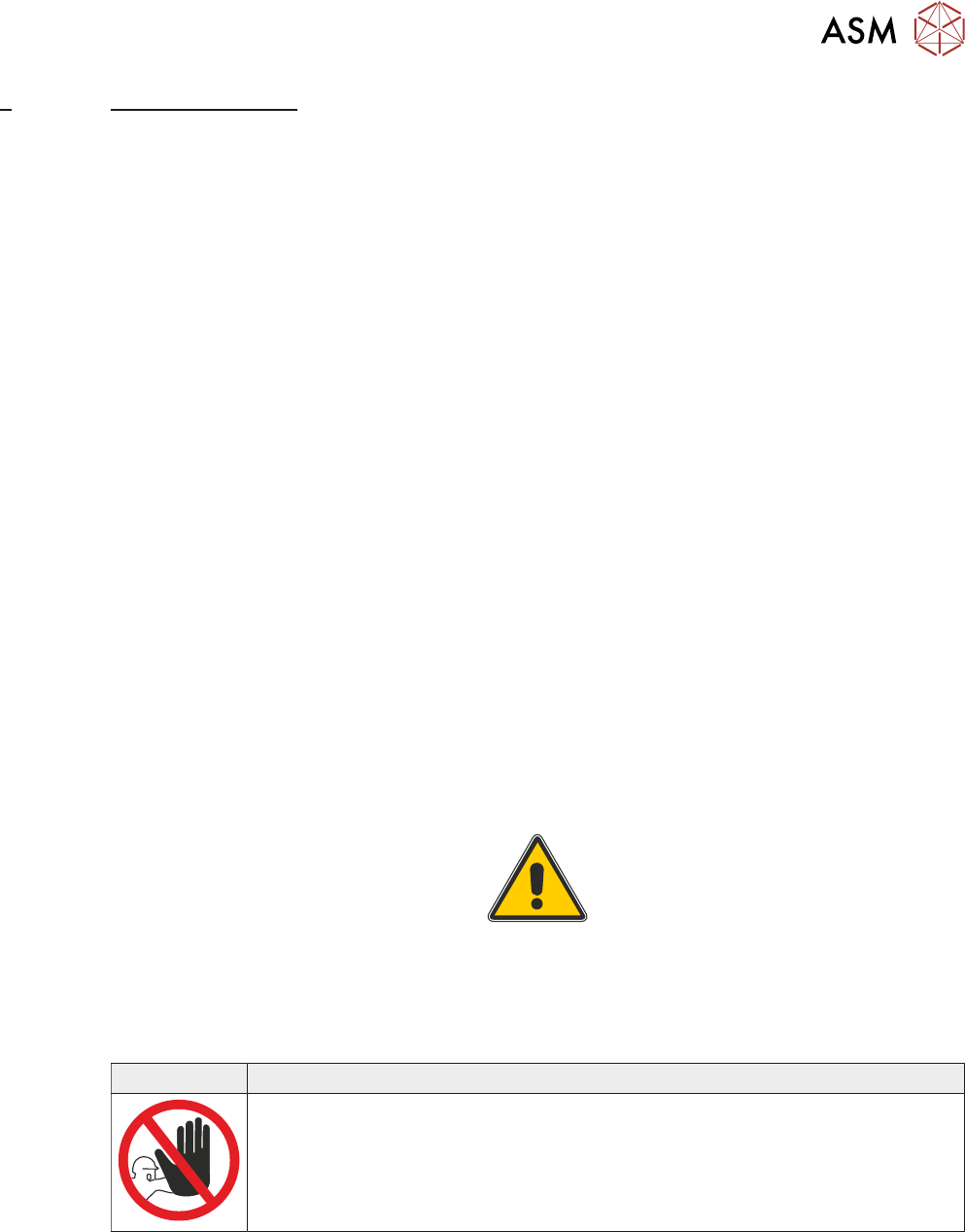
PROHIBITION
MACHINE COVERS. IN ORDER TO PROTECT PERSONNEL AND TO PRE-
VENT DAMAGE TO THE MACHINE, COVERS ARE FITTED TO THE MACHINE
FRAME. THESE PANELS MUST ONLY BE REMOVED BY SUITABLY QUALI-
FIED PERSONNEL.
3 SAFETY FEATURES
3.1 OVERVIEW
22 TECHNICAL REFERENCE MANUAL Vol 1 E By DEK 04/2019
3.1.2.2 Warning Notices
Warning notices draw the attention of users/maintainers to a potentially hazardous situation which,
if not avoided, could result in death or serious injury. The following table displays the warning labels
affixed to printer and/or displayed in the machine documentation.
Symbol Definition
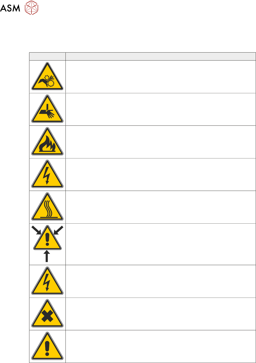
WARNING
MOVING PARTS. MOVING PARTS ARE PRESENT IN THE VICINITY OF THIS
WARNING LABEL, THESE PARTS HAVE THE POTENTIAL TO CAUSE IN-
JURY.
WARNING
BOARD CLAMPS. EXTREME CARE MUST BE EXERCISED WHEN WORKING
IN THE TOOLING AREA OF THE MACHINE TO AVOID INJURY. THE FOILS
ON THE FRONT AND REAR BOARD CLAMPS ARE VERY SHARP.
WARNING
FLAMMABLE. FLAMMABLE SUBSTANCES ARE PRESENT. KEEP AWAY
FROM HEAT, SOURCES OF IGNITION AND STATIC DISCHARGES. USE IN A
WELL VENTILATED AREA.
WARNING
LETHAL VOLTAGE. DANGEROUS VOLTAGES EXIST IN THIS EQUIPMENT.
ENSURE ALL ELECTRONIC COVERS AND MAIN MACHINE COVERS ARE
FITTED BEFORE OPERATING THIS EQUIPMENT.
WARNING
HOT SURFACES. THE SURFACE OF THIS COMPONENT OR SURROUND
AREA MAY BECOME HOT DURING PROLONGED OPERATION. CARE TO BE
TAKEN WHEN WORKING IN THE VICINITY OF THIS COMPONENT.
WARNING
COMPRESSED AIR. COMPRESSED AIR SHOULD NEVER IMPINGE UPON
THE BODY, PORTS, PIPES, ETC MUST NEVER BE BLOCKED BY HAND. BE-
FORE CONNECTING OR DISCONNECTING ANY PNEUMATIC COMPON-
ENTS, ENSURE THE COMPRESSED AIR SUPPLY HAS BEEN DISSIPATED
AND DISCONNECTED FROM THE MACHINE.
WARNING
E STOP CIRCUIT. THE E STOP ONLY ISOLATES THE DC SUPPLIES TO THE
MOTORS. LETHAL VOLTAGES ARE STILL PRESENT WITHIN THE MACHINE
AFTER THE E STOP HAS BEEN ACTIVATED.
WARNING
HARMFUL SUBSTANCES. CLEANING WIPES AND CLEANING SOLUTIONS
MAY CONTAIN SUBSTANCES HAZARDOUS TO HEALTH. WHEN USING
CLEANING WIPES AND CLEANING SOLUTIONS THE MANUFACTURER'S
SAFETY DATA SHEETS MUST BE STRICTLY ADHERED TO.
WARNING
MACHINE LIFTING. TO PREVENT SERIOUS INJURY TO PERSONNEL, DUR-
ING LIFTING AND TRANSPORTATION OPERATIONS, ENSURE THE MA-
CHINE IS LIFTED AND TRANSPORTED IN ACCORDANCE WITH INSTRUC-
TIONS DETAILED IN THIS SECTION.