03217917-01-01E By DEK Technical Reference Manual Vol 1_enPDFA.pdf - 第212页
15 BOARD STOP 15.6 ADJUSTMENTS AND SETTINGS 212 TECHNICAL REFERENCE MANUAL Vol 1 E By DEK 04/2019 15.6.5.3 Fitting the Remote Board Stop ► Fit the remote board stop base clamp locating nut (1) into the attachment slot (2…
15 BOARD STOP
15.6 ADJUSTMENTS AND SETTINGS
TECHNICAL REFERENCE MANUAL Vol 1 E By DEK 04/2019 211
15.6.5.2 External Services
► Select Shut Down.
► Select Continue.
► Switch the mains isolator to OFF.
► Disconnect the quick release mains air connection at the rear the machine.
► Remove the machine rear cover.
► Remove the right hand side safety cover.
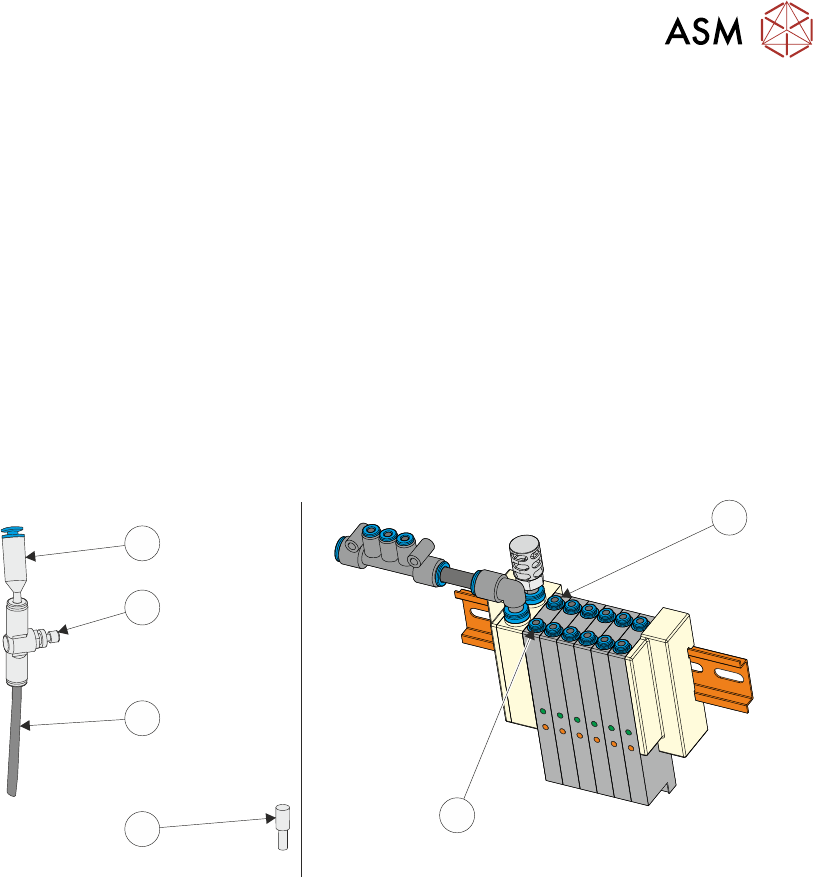
► At the board stop solenoid (16SOL14), on the pneumatic manifold at the rear of the machine:
► Remove the pipe marked Board Stop from the front port (A) (2).
► If an in-line flow controller is not already connected to the rear port (B) (1), remove the exist-
ing blanking plug (3) from the rear port (B) (1) and fit the in-line flow controller (5), via the
50mm x 4mm pipe (4) (both supplied with the remote board stop) to the rear port (B) (1). The
in-line flow controller (5) should have a self-seal connector (6) at its open end.
1
2
3
4
5
6
► Fit the pipe marked Remote/B/Stop Up - RH to the front port (A) (2).
► Fit the pipe marked Remote/B/Stop Down - RH to the in-line flow controller, self-seal con-
nector (6) fitted to the rear port (B) (1).
► Behind the front cover, mounted on the machine frame next to the 4 port USB hub:
1. Remove plug BPL6 from socket BSK6.
2. Connect plug BPL6A to socket BSK6.
► Fit the rear cover.
15 BOARD STOP
15.6 ADJUSTMENTS AND SETTINGS
212 TECHNICAL REFERENCE MANUAL Vol 1 E By DEK 04/2019
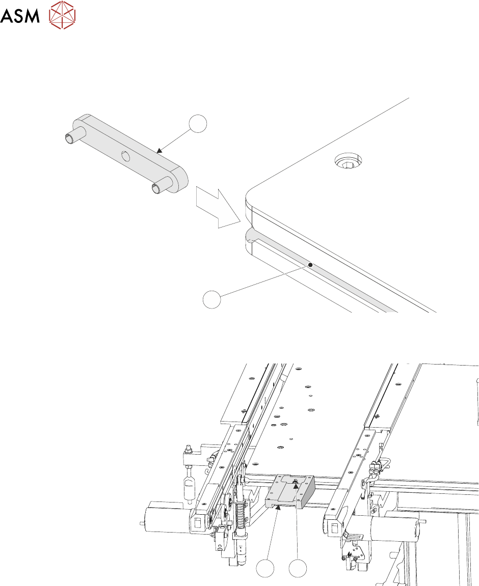
15.6.5.3 Fitting the Remote Board Stop
► Fit the remote board stop base clamp locating nut (1) into the attachment slot (2) on the right
hand side of the rising table.
1
2
► Attach the base clamp (4) to the locating nut (1), in the correct position in the Y axis for the
product, using a 4mm Allen key and M5 securing screw and washer (3).
4
3
► Mark the centre point, in the X axis, on the front of the product board.
► Place the product board on the rails with the board centre point at the Camera Reference Po-
sition (white dot on front rail).
► Before fitting the remote board stop assembly to the base clamp, ensure that the board stop is
configured for right hand side operation, 15.6.3 "Setting the Remote Board Stop" [}203]
refers.
15 BOARD STOP
15.6 ADJUSTMENTS AND SETTINGS
TECHNICAL REFERENCE MANUAL Vol 1 E By DEK 04/2019 213
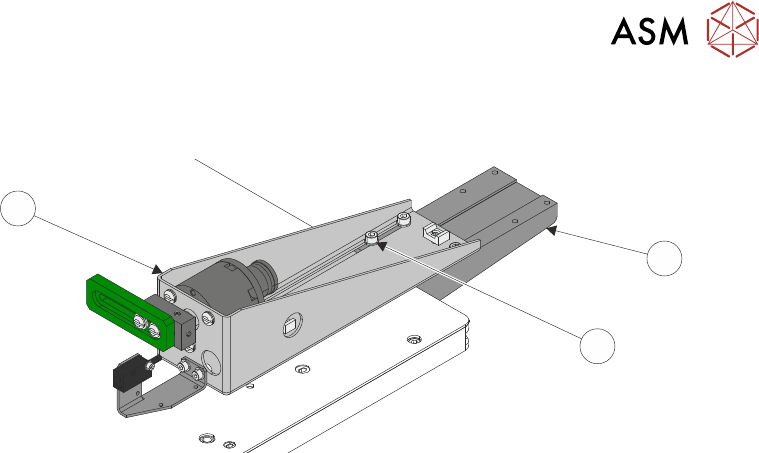
► Lay the remote board stop assembly (7) onto the base clamp (5) so that the board stop is
clear of the board.
7
5
6
► Using the appropriate slots, loosely secure the remote board stop assembly (7) to the base
clamp (5), using the four M5 cap head screws (6).
► Connect plug 8PL05 to socket 8SK05R.
► Connect the pipe marked Remote/B/Stop R1 to the in-line connector on the pipe marked 1 on
the remote board stop.
► Connect the pipe marked Remote/B/Stop R2 to the in-line connector on the pipe marked 2 on
the remote board stop.
► Refit the right hand side safety cover.
► Reconnect the mains air quick release connection to the machine.
► Switch the mains isolator to ON.
► Press the Start button.
► When prompted select Diagnostics.
► When prompted press the System button.
► Carry out 15.6.3 "Setting the Remote Board Stop" [}203].