03217917-01-01E By DEK Technical Reference Manual Vol 1_enPDFA.pdf - 第225页
15 BOARD STOP 15.7 CALIBRATION TECHNICAL REFERENCE MANUAL Vol 1 E By DEK 04/2019 225 15.7 CALIBRATION 15.7.1 Board Stop X Offset W ARNING BOARD CLAMPS. EXTREME CARE MUST BE EXERCISED WHEN WORKING IN THE TOOLING AREA OF T…
15 BOARD STOP
15.6 ADJUSTMENTS AND SETTINGS
224 TECHNICAL REFERENCE MANUAL Vol 1 E By DEK 04/2019
12
► Slide the remote board stop to the front of the machine, until it abuts the front rail.
► Close the front printhead cover.
► Press the System button.
► Select Back.
► Select Setup Product.
► Select Load Product.
► Select the product file to be used with the remote board stop.
NOTE
The selected product file must have a board width of 130mm or greater.
► Select Load.
► Select Back.
► Select Back.
► Open the front printhead cover.
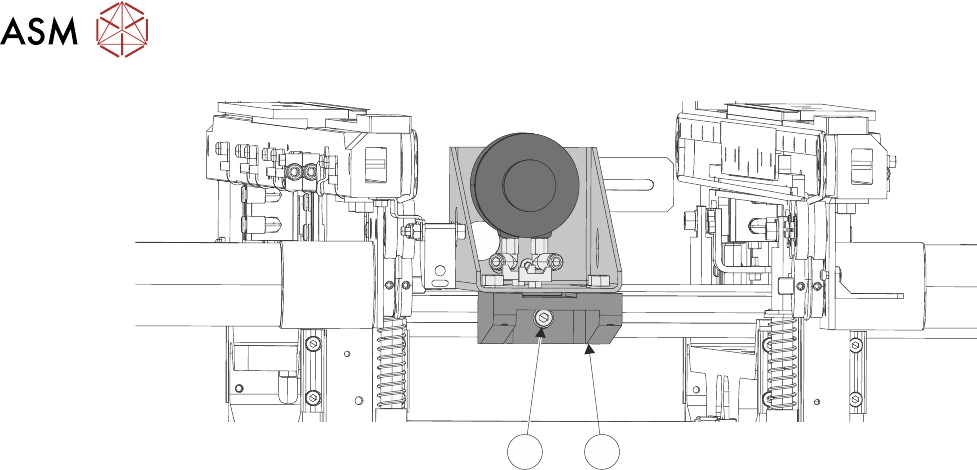
► Slide the remote board stop to the correct position in the Y axis, for the product to be printed
and tighten the securing screw at the bottom of the base clamp, using a 4mm Allen key.
► Carry out 15.6.3 "Setting the Remote Board Stop" [}203].
15 BOARD STOP
15.7 CALIBRATION
TECHNICAL REFERENCE MANUAL Vol 1 E By DEK 04/2019 225
15.7 CALIBRATION
15.7.1 Board Stop X Offset
WARNING
BOARD CLAMPS. EXTREME CARE MUST BE EXERCISED WHEN WORKING IN
THE TOOLING AREA OF THE MACHINE TO AVOID INJURY. THE FOILS ON THE
FRONT AND REAR BOARD CLAMPS ARE VERY SHARP.
The board stop X offset is the distance between the leading edge of the board and the centre of the
camera view whilst the board is at the board stop position.
► Place a board on the inroad conveyor.
► Select Maintenance.
► Select Calibrations.
► Select Board Stop X Offset from the table.
► Select Load Board.
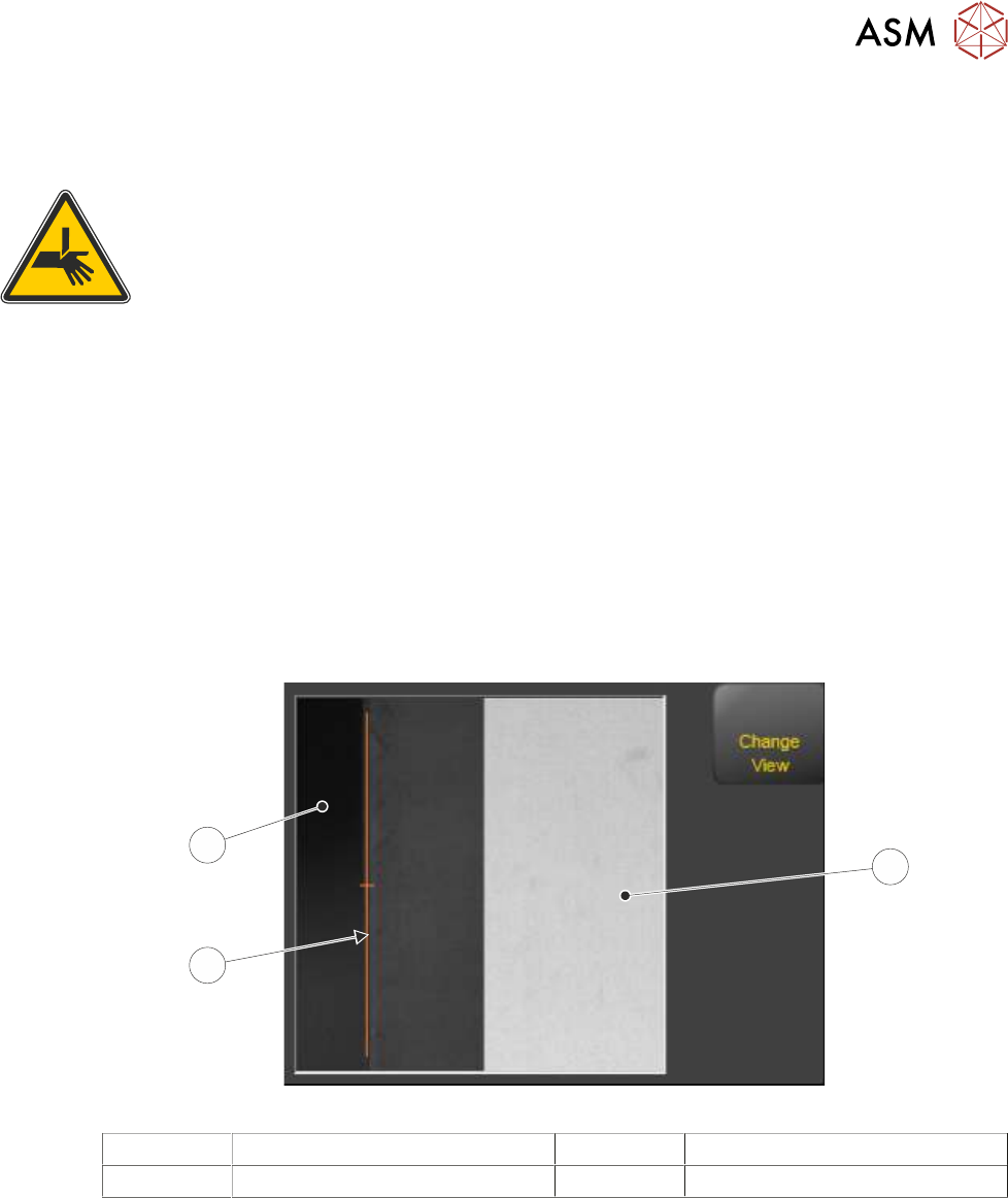
The board loads to the board stop. The board stop is retracted and the camera moves to-
wards the leading edge of the board by the distance stated in the board stop X offset para-
meter. If the offset is correct, the amber marker line in the vision window aligns with the edge
of the board.
1
3
2
1 Camera Looking Up 3 Board as seen by the Camera
2 Marker
NOTE
The vision view may display Single View (looking down on the board) or Split View (looking up and
down) depending on the camera fitted. The graphic above is showing Split View.
► If the offset is correct, Select Confirm. Go to Close Up.
► Select Board Stop X Offset.
► Increasing the value moves the board right of the amber marker. Decreasing the value moves
the board left. the nudge function can be used to make the move.
► Select Accept. The vision window updates with the new value.
► Repeat previous three Steps until the board edge matches up with the amber marker.
► Select Save And Exit.

15 BOARD STOP
15.7 CALIBRATION
226 TECHNICAL REFERENCE MANUAL Vol 1 E By DEK 04/2019
Close Up
► Remove the board.
► Select Back.
► Select Back.