03217917-01-01E By DEK Technical Reference Manual Vol 1_enPDFA.pdf - 第232页
16 TRANSPORT RAILS MODULE 16.3 PNEUMATIC SCHEMATIC 232 TECHNICAL REFERENCE MANUAL Vol 1 E By DEK 04/2019 16.3 PNEUMATIC SCHEMATIC 5/2 16S O L10 A B Clamp Speed Control Unclamp Delay Control Fitted at Solenoid V alve on R…
16 TRANSPORT RAILS MODULE
16.2 ELECTRICAL SCHEMATIC
TECHNICAL REFERENCE MANUAL Vol 1 E By DEK 04/2019 231
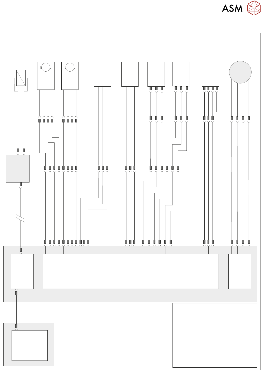
16.2 ELECTRICAL SCHEMATIC
Machine PC
Motherboard
Machine Control Enclosure
Front Belt
Drive (8M03)
Rear Belt
Drive (8M04)
DIG IN 10
DIG IN 11
Rail Lift Left
(8SE5)
Board at Right
Sensor (8SE7)
Board at Left
Sensor (8SE8)
8PL10
8PL04
M36PL17
8PL03
Sig
Sig
+12V
+12V
+12V
0V
0V
8PL12
DIG IN 6
Sig
0V
M36PL22
Moving Rail
Stepper
Motor 2B-
Motor 2A-
Motor 2B+
Motor 2A+
8PL20
8M2
Dual Stepper
X3
NextMove
Interface Card
X4
M
Enable
Direction
24V SW
0V
M
Enable
Direction
24V SW
0V
8SK21
8PL22
8SK23
M36PL18
!DIG OUT 3
DIG OUT 3
DIG OUT 2
DIG OUT 2
NextMove ES
(I/O Node 1)
X5
Board Clamp/
Snugger Solenoid
(16SOL10)
DIG OUT 9
GND
Main Machine
I/O Node 2
N2PL4
CAN Bus
N2SK2
USB
Moving Rail
Home (8SE6)
8PL26
M36PL19
+12V
0V
Sig
DIG IN 5
Rail Lift Right
(8SE4)
+12V
8PL15
DIG IN 7
Sig
0V
NOTES
1.The breaks in the CAN Bus
chain reflect that additional
I/O Nodes may be fitted,
refer to Machine Control
chapter for the complete
CAN Bus chain.
2. Refer to circuit 185231
for the following options:
Heavy Board Rail
Dual Speed Motor
Remote Board Stop
Top Referencing System
Vacuum and Grid-Lok
Tooling.
(L)
16 TRANSPORT RAILS MODULE
16.3 PNEUMATIC SCHEMATIC
232 TECHNICAL REFERENCE MANUAL Vol 1 E By DEK 04/2019
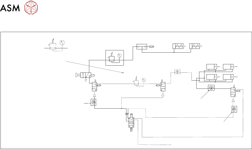
16.3 PNEUMATIC SCHEMATIC
5/2
16SOL10
A B
Clamp
Speed
Control
Unclamp Delay Control
Fitted at Solenoid
Valve on Rear of M/C
Board Clamps
Snuggers
Out
In
Pressure Control
Snuggers On
Board Clamp
Reg (optional)
Snugger Delay
(Control)
In
Out
Mains Input
Out To Board
Clamps
16 SOL10 (A) In
E By DEK Board Clamp Regulator
NOTE
Only one regulator fitted;
dependent on option in use.
16 TRANSPORT RAILS MODULE
16.4 ADJUSTMENTS AND SETTINGS
TECHNICAL REFERENCE MANUAL Vol 1 E By DEK 04/2019 233
16.4 ADJUSTMENTS AND SETTINGS
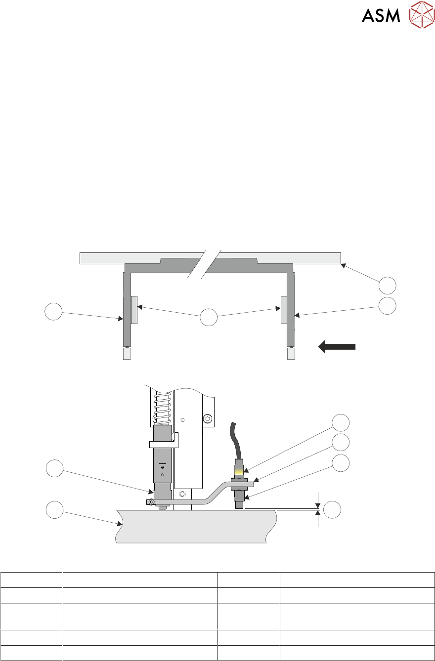
16.4.1 Rail Lifted Sensors
► Select Maintenance.
► Select Diagnostics.
► Select Confirm.
► From the displayed table, select Rising Table.
► Select Home Table.
► Select Back.
► From the displayed table, select Rail System from the table.
► Select Home Rails.
► Remove the left and right hand side safety covers to gain access to the rear rail.
► Identify the rear right rail transport leg and the rail stop bar (clatter bar).
View on Arrow
4
3
1
2
5
6
7
8
9
10
1 Rear Rail 6 Sensor Support Bracket
2 Right Transport Leg 7 Sensor
3 Linear Bearings 8 3.5mm GO
4mm NO GO
4 Left Transport Leg 9 Rail Stop Bar (Clatter Bar)
5 Sensor LED 10 Shock Absorber
► Adjust the sensor position, so that a 3.5mm gauge fits between the sensor and the top face of
the clatter bar and a 4mm gauge does not fit.
► Repeat previous Step for left hand end of the rear rail.
► Select Board Width parameter.
► Enter a value of 40.5mm (minimum board width), and select Accept.